Download
1 / 23
230 likes | 477 Vues
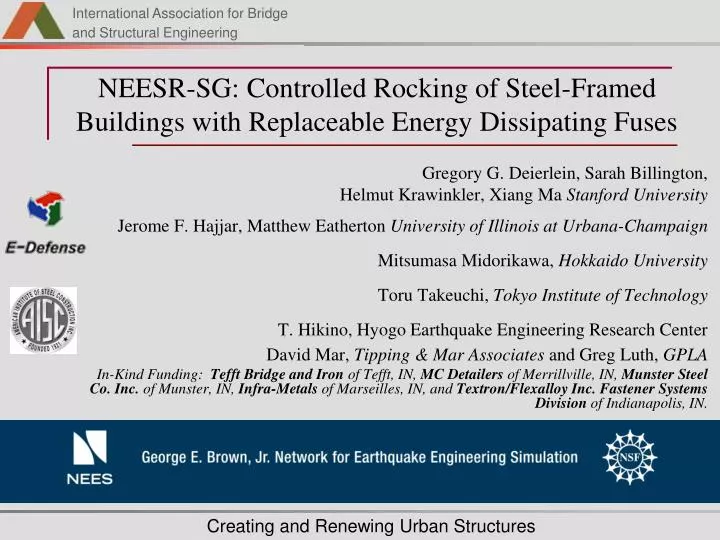
NEESR-SG: Controlled Rocking of Steel-Framed Buildings with Replaceable Energy Dissipating Fuses. Gregory G. Deierlein, Sarah Billington, Helmut Krawinkler, Xiang Ma Stanford University Jerome F. Hajjar, Matthew Eatherton University of Illinois at Urbana-Champaign

E N D
NEESR-SG: Controlled Rocking of Steel-Framed Buildings with Replaceable Energy Dissipating Fuses Gregory G. Deierlein, Sarah Billington, Helmut Krawinkler, Xiang Ma Stanford University Jerome F. Hajjar, Matthew Eatherton University of Illinois at Urbana-Champaign Mitsumasa Midorikawa, Hokkaido University Toru Takeuchi, Tokyo Institute of Technology T. Hikino, Hyogo Earthquake Engineering Research Center David Mar, Tipping & Mar Associates andGreg Luth, GPLA In-Kind Funding: Tefft Bridge and Iron of Tefft, IN, MC Detailers of Merrillville, IN, Munster Steel Co. Inc. of Munster, IN, Infra-Metals of Marseilles, IN, and Textron/Flexalloy Inc. Fastener Systems Division of Indianapolis, IN.
Key Short Comings of Modern Seismic Design Throw-away technology: Structure and Architecture absorbs energy through damage Large Inter-story Drifts: Result in architectural & structural damage High Accelerations: Result in content damage & loss of function Deformed Section – Eccentric Braced Frame
New System Develop a new structural building system that employs self-centering rocking action and replaceable* fuses to provide safe and cost effective earthquake resistance. Shear Fuse Post-tensioning *Key Concept – design for repair
Controlled Rocking System Component 3 – Replaceable energy dissipating fuses take majority of damage Component 2 – Post-tensioning strands bring frame back down during rocking Component 1 – Stiff braced frame, designed to remain essentially elastic - not tied down to the foundation. Bumper or Trough
Pretension/Brace System Fuse System c b c d e b Base Shear a,f Base Shear Fuse Strength Eff. Fuse Stiffness a d PT Strength g Drift Frame Stiffness g f e Drift b c Origin-a – frame strain + small distortions in fuse a – frame lift off, elongation of PT b – fuse yield (+) c – load reversal (PT yields if continued) d – zero force in fuse e – fuse yield (-) f – frame contact f-g – frame relaxation g – strain energy left in frame and fuse, small residual displacement Base Shear 2x Fuse Strength d a PT Strength e f PT – Fuse Strength g Drift Combined System
Attributes of Fuse high initial stiffness large strain capacity energy dissipation Candidate Fuse Designs ductile fiber cementitious composites steel panels with slits low-yield steel mixed sandwich panels damping devices Phase I: Shear Fuse Testing Panel Size: 400 x 900 mm
Butterfly link: b/a Rectangular link: b/t and L/t Welded end Buckling-restrained Fuse Configurations thickness t h L a b B
Testing Results: Butterfly Links B56-09 B36-10 B37-06 B14-02
Butterfly Links: Load-Deformation B36-10 B56-09 B37-06 B14-02
General Specimen Design Phase II: Half-Scale System Tests In the Rig
Network for Earthquake Engineering Simulation (NEES) Test Setup at MUST-SIM Facility Loading and Boundary Condition Box (LBCB) Loading Beam Applies Loads to the Two Frames Load Cell Pins Provide Load Data and Feedback for Control Reaction Wall Anchorage Plate for the Post-Tensioning Bumpers Restrain Horizontal Movement (Not Shown Here)
Test Results – Hysteretic Behavior Test A2 Test A1
Test Results – Post Tensioning Force Test A2 Test A1
Test Results – Left Frame Column Uplift Test A2 Test A1
Test Results – Fuse Shear Strain Test A2 Test A1
Test Frame Test-bed Unit
Controlled Rocking System Test at E-Defense (2009) • Large (2/3 scale) frame assembly • Validation of dynamic response and simulation • Proof-of-Concept • construction details • re-centering behavior • fuse replacement • Collaboration & Payload Projects
Conclusions • The controlled rocking system exhibits excellent self-centering and energy dissipating response. All indicators show that the system is constructable and viable for practice. • The controlled rocking system will reduce life cycle costs by reducing structural repair costs after an earthquake. • Butterfly steel plate shear fuses, tested at Stanford University, were able to sustain cyclic deformations as large as 25% shear strain or more and still absorb seismic energy. • Half scale tests at University of Illinois are in progress. Tests A1, A2, and A3 are complete. More tests to come. • Two-thirds scale shake table tests on a planar frame at E-Defense next summer will further validate system performance. • Design recommendations will be develoeped to allow implementation in practice.
Video of Specimen A1 Six ¼” fuses buckled late in the loading history; Peak drift: 3%; Peak shear strain: 11%