Download
1 / 39
410 likes | 630 Vues
MUST-SIM. Controlled Rocking of Steel-Framed Buildings with Replaceable Energy Dissipating Fuses. Matt Eatherton, MS SE University of Illinois at Urbana-Champaign. MUST-SIM Meeting February 5, 2007. Organization. Introduction Controlled Rocking System Parametric Study & Prototype Building

E N D
MUST-SIM Controlled Rocking of Steel-Framed Buildings with Replaceable Energy Dissipating Fuses Matt Eatherton, MS SE University of Illinois at Urbana-Champaign MUST-SIM Meeting February 5, 2007
Organization • Introduction • Controlled Rocking System • Parametric Study & Prototype Building • UIUC Half-Scale Test Program • Conclusions
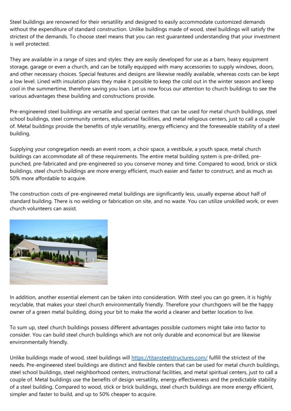
Current Building Codes - Expected Building Performance? Two story steel-framed office building in Santa Clarita suffered residual drift in the first story due to the Northridge Earthquake. Building with a Red Tag restricting access after the Northridge Earthquake Industrial Structure that experienced brace buckling and residual drift during Loma Prieta From EERI Earthquake Recon. Report, Jan. 1996 & May 1990
Current Building Codes - Expected Building Performance? • Seismic loads prescribed in current building codes assume a considerable amount of inelastic damage in structural elements. • In a severe seismic event, structural damage can be distributed throughout the structure and extensive enough to make repair uneconomical. • Residual drifts also make repair difficult if not financially unreasonable. • The goal of current building codes is to provide life safety during large earthquakes – not limiting structural damage or ensuring repairability. • To construct a building that is easy to repair, two attractive performance goals would be to 1.eliminate residual drifts and 2.concentrate all the structural damage in replaceable fuses.
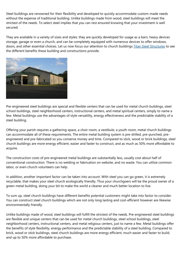
Controlled Rocking System Component 3 – Replaceable energy dissipating fuses take majority of damage Component 2 – Post-tensioning strands bring frame back down during rocking Component 1 – Stiff braced frame, designed to remain essentially elastic - not tied down to the foundation. Bumper or Trough
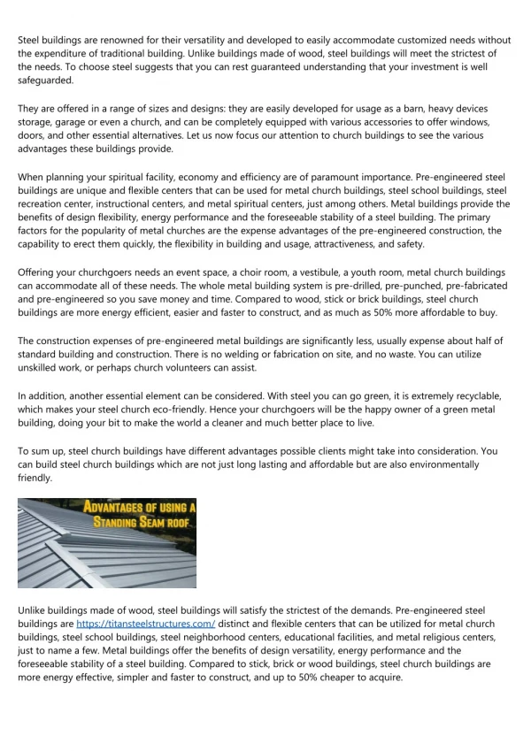
Controlled Rocking Systemin the Rocked Configuration Corner of frame is allowed to uplift. Fuses experience more shear strain than drift angle – amplification One challenge is limiting floor damage while transferring diaphragm shear to frame.
Variations • Fuse Type / Material • Steel Panel • Slit Steel Panel • Butterfly Panel • Engineered Cementitous Composite (ECC) Panels with various reinforcement schemes. • Aluminum • Others. . .
Variations (Cont’d) • Fuse Distribution Among Stories - may not need fuses at every story • Frame Bracing Configuration 1. Chevron 2. Chevron at top to resist post-tensioning load and single braces below 4. Steel plate shear walls (SPSW) 3. Two-Story X
Variations (Cont’d) • Post-Tensioning Location – at columns or in middle • Single Frame vs. Dual Frame Dual Frame with P/T at Mid-point of Frame Dual Frame with P/T at Columns (P/T loops in foundation to allow enough P/T strain capacity) Single Frame with Fuses on Either Side
Research Program Research Team: PI Greg Deierlein – Project Manager, Stanford University Co-PI Sarah Billington – ECC & HPFRCC Fuses, Stanford Unviersity Co-PI Jerome Hajjar – Simulation and Half-Scale Tests, University of Illinois Helmut Krawinkler, Stanford University Mitsumasa Midorikawa – E-Defense, Building Research institute in Japan David Mar - Industry Collaborator, Tipping and Mar Engineers Current Graduate Students: Xiang Ma (Stanford), Eric Borchers (Stanford), Matt Eatherton (UIUC) Past Graduate Students: Paul Cordova (Post-Doc at Stanford), Kerry Hall (UIUC), Project is funded by a grant from NSF - NEESR-SG E-DEFENSE JAPAN
Research Program • Schematic Design and Analysis (Entire Team) • Single degree of freedom study. • Iterations on system design (such as variations described above). • Planer MDOF models. • Fuse Panel Design and Testing (Stanford) • Engineered Cementitous Composites (ECC) panels. • Steel slit panels. • Steel butterfly panels. • Parametric Study (UIUC) • Define a prototype structure. • Nonlinear time history analyses to examine effect of each variable. • Use results to inform decisions about testing program.
Research Program • Half-Scale Tests (UIUC) • Test several half-scale specimens representing prototype frames. • Validate the performance of the controlled rocking system. • Examine forces realized in the fuses. • Study and improve details not common in steel structures. • Large-Scale Shake Table Tests (E-Defense / Stanford) • Study ability of system to self-center. • Further validation of the system performance. • Design Implications and Recommendations (Entire Team) • Characterize performance of the controlled rocking system • Summarize design recommendations
Controlled Rocking System – Mechanism for Resisting Overturning FPT = Initial post-tension force Vp = Fuse yield strength in shear Overturning moment = Resistance comes from Post-Tensioning and Fuses: In an LRFD context use a resistance factor to design: Can also include gravity loads
Controlled Rocking System – Mechanism for Self-Centering In the rocked configuration, the fuses resist self-centering. The restoring moment due to P/T must overcome the restoring resistance: • Other sources of resistance not considered in this equation include: • Stiffness of gravity system • Stiffness of interior partitions that have undergone inelastic damage • P-delta effect • Can also include effect of gravity load in restoring force.
Controlled Rocking System –Fuse Shear Strain Capacity Using small angle assumption: Shear strain in the fuses is amplified compared to the roof drift ratio (RDR). Fuse Shear Strain, g = Example:
Controlled Rocking System – Representative Hysteretic Response • FLAG SHAPED HYSTERESIS • Begin Loading • Frame Uplifts • Fuses Yield • Load reversal. If pushed far enough P/T would yield • Zero force in fuses • Fuses yield in other direction • Frame sets back down and forces in the frame relax. • Elastic strain energy remains in frame and fuses 3 4 5 2 7 1 6 8
Controlled Rocking System – Other Considerations • Global Overturning (FPT > Vp) • Initial P/T stress: Stressing the P/T strands 0.4 Fu may require special procedures to anchor post-tensioning (post-blocking). • P/T strain capacity: If performance criteria includes not replacing P/T after a severe earthquake then ensure adequate strain capacity. Preventing Global Overturning
Prototype Structure Use prototype structure to apply controlled rocking to a realistic structure Based on SAC Building configuration Tests and analysis simulate the controlled rocking frames in this structure.
Ground Motions • Based on Medina Dissertation (2002) • Used the LMSR-N group (40 grnd mtns) • Design spectrum is based on site in LA • Scaled to one-second spectral accel. • Scaled to three hazard levels • Ground motions that required scaling greater than 4.0 were thrown out.
Parametric Study • Parameters Studied • A/B ratio – geometry of frame • Overturning Ratio (OT) – ratio of resisting moment to design overturning moment. OT=1.0 corresponds to R=8.0, OT=1.33 means R=6.0, and OT=0.8 means R=10. • Self-Centering Ratio (SC) – ratio of restoring moment to restoring resistance. • Initial P/T stress • Frame Stiffness • Fuse type including degradation
Parametric Study Results OT=1.0 SC=1.0 A/B=2.3 SC=1.0 A/B=2.3 OT=1.0
Parametric Study Results OT=1.0 SC=1.0 A/B=2.3 SC=1.0 A/B=2.3 OT=1.0
Parametric Study Results OT=1.0 SC=1.0 A/B=2.3 SC=1.0 A/B=2.3 OT=1.0
Parametric Study - Conclusions • Reduction in the A/B ratio resulted in a decrease in the fuse shear strains, but requires steeper bracing in the braced frames, and yields slightly higher displacements. • Higher OT factors minimize displacement response, including residual displacements and fuse shear strain demands. The advantages of increasing OT must be tempered by the cost of larger forces that must be transmitted through the frame and foundation, and slightly larger accelerations. • The system exhibited excellent self-centering capability. The SC ratio does not need to be larger than 1.0 to self-center the system, but configuration must be checked to preclude global overturning. Also, it is expected that upon removal of the fuses (for replacement), any residual uplift or roof drift would be eliminated. • The system has to rock to work. None of the configurations considered eliminated uplift for even the smaller event considered (50% in 50 years). The OT ratio had the most effect in limiting peak uplift. • Peak roof drift ratios and peak uplifts were in acceptable ranges even for OT = 0.75 (R=10). • Based on median for 2% in 50 year event, the following are limits that might be imposed on fuse design: • For A/B ratio = 1.5, use fuses with shear strain capacity of 0.08 • For A/B ratio = 2.0, use fuses with shear strain capacity of 0.10 • For A/B ratio = 2.5, use fuses with shear strain capacity of 0.11 • For A/B ratio = 3.0, use fuses with shear strain capacity of 0.13
Potential Fuse Shear Strain Capacity Fuse tests are underway. Fuse configurations include steel slit panel, steel butterfly panel, and ECC panels
UIUC Half-Scale Tests • Goals: • To test and improve details – post-tensioning and base connections are not typical to steel structures. • Study the forces realized in the fuses and distribution of force between fuses. Geometric nonlinearity and indeterminacy creates complexity. • Examine effect of out-of-plane motion while rocking. • Determine whether typical P/T strands and anchorage can be stressed to yield without fracturing or slipping. • Establish whether there is inelasticity or relaxation in the P/T that would require replacement or re-stressing. • Investigate whether inelasticity occurs in the frame. VERIFY THE PERFORMANCE OF THE SYSTEM FOR IMPLEMENTATION IN PRACTICE
UIUC Half-Scale Tests Front View Side View
UIUC Half-Scale Tests Test B1 – A/B=2.5 Test A3 – A/B=1.75
Proposed Mixed Mode Control The horizontal movement of the Left LBCB would be used to control the test. The Right LBCB will match the horizontal force in the left LBCB. This will apply the same amount of load to both frames, but allow differential rocking between the frames.
EBF Loading Protocol From Richards and Uang (2006) and Okazaki (2005)
Hybrid Simulation • Reasons for conducting the hybrid simulation: • Ground motions will be applied in both directions (parallel and perpendicular to the frame being tested), the ability of the frame to withstand out-of-plane motion, and rock while sustaining out-of-plane rotation will be examined. • The lateral stiffness of the gravity framing and/or the stiffness of interior partitions will be modeled, so the ability of the system to self-center in a real building can be demonstrated. • The level of damage and repairability of the system after a realistic earthquake motion will be demonstrated. • We may try to model a building taller than 3 stories. • Account for P-Delta effect with a leaning column in the model.
Conclusions / Summary • Seismic loads prescribed in current building codes assume considerable inelasticity in the structure during a severe earthquake. This can result in structural damage and residual drift that cannot be economically repaired. • To provide a building that is relatively easy to repair after an earthquake, two attractive performance criteria are: • Eliminate residual drift. • Concentrate bulk of structural damage in replaceable fuses. • The controlled rocking system satisfies these performance goals. • The controlled rocking system consists of three major components: • Stiff steel braced frame designed to remain essentially elastic, but not tied down to the foundation. • Post-tensioning that provides self-centering capability. • Highly ductile energy dissipating fuses.
Conclusions / Summary • A multi-institution, international research project is underway to examine, improve, and validate the performance of this innovative system. • A parametric study was conducted to optimize A/B ratio, OT ratio, and SC ratio. Results were presented. • Some considerations in the design of the controlled rocking system include: • Proportioning fuses and P/T to resist overturning, but still self-center. • Insuring enough P/T strain capacity. • Using fuses with enough shear strain capacity based on frame geometry (fuse shear strain is amplified compared to roof drift ratio). • Preclude global overturning.
Conclusions / Summary • Half-scale tests will be conducted later this year at the UIUC MUST-SIM Facility to improve details and validate the performance of the controlled rocking system for implementation in practice. • Loading protocol has significant effect on EBF link tests. A loading protocol based on state-of-the-art EBF protocol will be used. • Hybrid simulation tests will further validate the system performance and demonstrate the self-centering and repairability of the controlled rocking system when subjected to a realistic ground motion.
Controlled Rocking of Steel-Framed Buildings with Replaceable Energy Dissipating Fuses QUESTIONS? Matt Eatherton, MS SE University of Illinois at Urbana-Champaign