Download
1 / 57
3.61k likes | 7.68k Vues
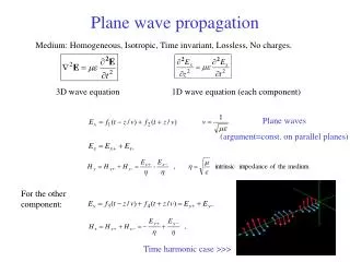
RADIO WAVE PROPAGATION. Presented by : Rajni Asstt . Professor(ECE) SBSSTC,Ferozepur. x. Electric Field, E. Magnetic Field, H. y. Direction of Propagation. z. RADIO WAVES. Electromagnetic Wave(Radio Waves) travel with a vel . of light.

E N D
RADIO WAVE PROPAGATION Presented by : Rajni Asstt. Professor(ECE) SBSSTC,Ferozepur
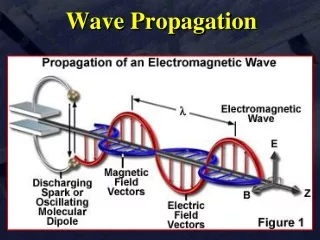
x Electric Field, E Magnetic Field, H y Direction of Propagation z RADIO WAVES Electromagnetic Wave(Radio Waves) travel with a vel. of light. These waves comprises of both Electric and Magnetic Field. The two fields are at right-angles to each other and the direction of propagation is at right-angles to both fields. The Plane of the Electric Field defines the Polarisation of the wave.
POLARIZATION The polarization of an antenna is the orientation of the electric field with respect to the Earth's surface. Polarization of e.m. Wave is determined by the physical structure of the antenna and by its orientation. Radio waves from a vertical antenna will usually be vertically polarized. Radio waves from a horizontal antenna are usually horizontally polarized.
Ground Waves or Surface Waves Ground Waves or Surface Waves • Frequencies up to 2 MHz • follows the curvature of the earth and can travel at distances beyond the horizon (upto some km) • must have vertically polarized antennas • strongest at the low- and medium-frequency ranges • AM broadcast signals are propagated primarily by ground waves during the day and by sky waves at nightis a Surface Wave that propagates or travels close to the surface of the Earth. It follows contour of the earth
Ground-Wave Propagation Ground or surface wave radiation from an antenna.
Ground Wave Propagation Advantages • Given enough power they can be used to communicate between any two points in the world • They are relatively unaffected by changing atmospheric conditions like sky waves.
Ground Wave Propagation (Contd.) • Disadvantages • Requires relatively high transmission power • They are limited to very low, low and medium frequencies which require large antennas • Losses on the ground vary considerably with surface material • Ground Wave get attenuated • due to earth imperfection, absorption and reflection by earth surface and attenuation increases with frequency. • by the tilt in the wave as it progresses along curvature of earth. Due to this horizontal component of electric field get shorted , which reduces strength of electric field.
Space Wave Propagation • This type of radio waves include radiated energy that travels in the lower few miles of the earth’s atmosphere. They include both direct and ground reflected waves. • A high gain and horizontally polarized antenna is thus highly recommended. • The field intensity at the receiving antenna depends on the distance between the two antennas and whether the direct and ground reflected waves are in phase.
Space Wave Propagation Radio Wave Propagation through Space: Direct Waves • A direct wave, or space wave, travels in a straight line directly from the transmitting antenna to the receiving antenna. Direct-wave radio signaling is often referred to as line-of-sight communication. • Direct or space waves are not refracted, nor do they follow the curvature of the earth. These waves are deviated (reflected) by obstructions and cannot travel over the horizon or behind obstacles. Line-of-Sight Propagation
Space Wave Propagation • At higher frequencies and in lower levels of the atmosphere, any obstruction between the transmitting antenna and the receiving antenna will block the signal. • Line-of-sight communication is characteristic of most radio signals with a frequency above 30 MHz, particularly VHF, UHF, and microwave signals.
SPACE WAVE(Line of Sight waves) Line of sight waves • travel directly from an antenna to another without reflection on the ground. • Occurs when both antennas are within line of sight of each another, distance is longer that line of sight because most space waves bend near the ground and follow practically a curved path. • Antennas must display a very low angle of emission in order that all the power is radiated in direction of the horizon instead of escaping in the sky.
Line-of-Sight Equations • Optical line of sight • Effective, or radio, line of sight • d = distance between antenna and horizon (km) • h = antenna height (m) • K = adjustment factor to account for refraction
Space-Wave Propagation (Line of Sight Propagation) • Maximum distance between two antennas for LOS propagation: • h1 = height of antenna one • h2 = height of antenna two Line-of-sight comm. by direct or space waves
LOS Wireless Transmission Impairments Attenuation and attenuation distortion Free space loss Noise Atmospheric absorption Multipath Refraction Thermal noise
Space-Wave Propagation Radio-Wave Propagation Through Space: Space Waves • Repeater stations extend the communication distance at VHF, UHF, and microwave frequencies. • A repeateris a combination of a receiver and a transmitter operating on separate frequencies. • The receiver picks up a signal from a remote transmitter, amplifies it, and retransmits it (on another frequency) to a remote receiver. • Repeaters are widely used to increase the communication range for mobile and handheld radio units.
Space Wave Propagation Radio-Wave Propagation Through Space: Space Waves • In a trunked repeater system,multiple repeaters are under the control of a computer system that can transfer a user from an assigned but busy repeater to another, available repeater, thus spreading the communication load. • Communication satellitesact as fixed repeater stations. • The receiver-transmitter combination within the satellite is known as a transponder.
Sky Wave Propagation • Sky Wave: • The propagation of Space and Ground waves are limited by the curvature of earth. • So for long distance comm. of thousands of Km or more are performed by Sky waves or ionospheric waves. • Also Known as Skip/ Ionospheric/ Hop/ wave. • HF radio communication (2 and 30 MHz) is a result of sky wave propagation. • Examples:Amateur radio
Sky Wave Propagation • Signal reflected from ionized layer of atmosphere back down to earth • Signal can travel a number of hops, back and forth between ionosphere and earth’s surface • Reflection effect caused by refraction
Sky-Wave Propagation Sky wave propagation
Sky-Wave Propagation (Related terms) • Sky-wave propagation refers to radio wave propagation via the ionosphere. Each reflection from the ionosphere is a hop. • Reception of sky-wave propagation is called skip. • The skip zone is the region between the max. ground-wave and min. sky-wave where a station can not be heard.
Sky-Wave Propagation • The higher the region in the ionosphere where the hop occurs, the greater the distance the wave can travel. • F2 skip can travel up to 2500 miles • E skip can travel up to 1200 miles Sky wave propagation
The virtual height is the height from which the radio wave appears to be reflecting.
Sky-Wave Propagation • Sky-wave propagation can include multiple hops between the Earth and the ionosphere. • Sky-wave signals due to fluctuations in the ionosphere which can create multiple paths for the signal (multipath). The combination of multipath signals can cause some distortion or fading. • If the ionosphere is very dense, then the critical angle is high and short skip is possible. • Short skip distances are much shorter than the usual skip distances. • Short skip on the 10 M band is a good indicator that sky-wave propagation is possible on 6 M.
Ionospheric Propagation For many years, numerous organisations have been employing the High Frequency (HF) spectrum to communicate over long distances. It was recognised in the late 30's that these communication systems were subject to marked variations in performance. It was hypothesised that most of these variations were directly related to changes in the ionosphere.
Ionospheric Propagation (Contd.) Considerable effort was made to investigate ionospheric parameters and determine their effect on radio waves and the associated reliability of HF circuits. World-wide noise measurement records were started and steps were taken to record observed variations in signal amplitudes over various HF paths.
Ionospheric Propagation (Contd.) The results of this research established that ionised regions ranging from approximately 70 to 1000 km above the earth's surface provide the medium of transmission for electromagnetic energy in the HF spectrum (2 to 30 MHz) and that most variations in HF system performance are directly related to changes in these ionised regions. The ionisation is produced in a complex manner by the photoionization of the earth's high altitude atmosphere by solar radiation.
Ionospheric Propagation(Contd) Within the ionosphere, the recombination of the ions and electrons proceeds slowly enough (due to low gas densities) so that some free electrons persist even throughout the night. In practice, the ionosphere has a lower limit of 50 to 70 km and no distinct upper limit, although 1000 km is somewhat arbitrarily set as the upper limit for most application purposes.
Ionospheric Propagation(Contd.) The vertical structure of the ionosphere is changing continuously. It varies from day to night, with the seasons of the year, and with latitude. Furthermore, it is sensitive to enhanced periods of short-wavelength solar radiation accompanying solar activity. In spite of all this, the essential features of the ionosphere are usually identifiable, except during periods of unusually intense geomagnetic disturbances.
PREDICTABLE IONOSPHERIC PARAMETERS The presence of free electrons in the ionosphere produces the reflecting regions important to High Frequency (HF) radio-wave propagation. In the principal regions, between the approximate heights of 75 km and 500 km, the electrons are produced by the ionising effect of ultraviolet light and soft x-rays from the sun. for convenience in studies of radio-wave propagation, the ionosphere is divided into three regions defined according to height and ion distribution: the D,E, and F regions.
Ionospheric Layers • Each region is subdivided into layers called the D, E, F1, and F2 layers, also according to height and ion distribution. • These are not distinctly separated layers, but rather overlapping regions of ionisation that vary in thickness from a few kilometres to hundreds of kilometres. • The number of layers, their heights, and their ionisation (electron) density vary both geographically and with time. • At HF all the regions are important & must be considered inpredicting the operational parameters of radiocommunication circuits.
THE IONOSPHERIC LAYERS CONT’D D layer: - is the innermost layer, 50 km to 90 km above the surface of the Earth. when the sun is active with 50 or more sunspots, During the night cosmic rays produce a residual amount of ionization as a result high-frequency (HF) radio waves aren't reflected by the D layer. • The D layer is mainly responsible for absorption of HF radio waves, particularly at 10 MHz and below, with progressively smaller absorption as the frequency gets higher. The absorption is small at nightand greatest about midday. The layer reduces greatly after sunset. A common example of the D layer in action is the disappearance of distant AM broadcast band stations in the daytime.
THE IONOSPHERIC LAYERS CONT’D D layer • Because of the low electron density, the D region doesnot reflect useful transmissions in the frequency range above 1 MHz. • The electron density is relatively small compared with that of the other regions, but, because of collisions between the molecules of the atmosphere and free electrons excited by the presence of an electromagnetic wave, pronounced energy loss occurs. • This energy loss, dissipated in the form of thermal energy of the electrons or thermal (electromagnetic) noise, is termed absorption.
THE IONOSPHERIC LAYERS(Contd.) The E layer: • is the middle layer, 90 km to 120 km above the surface of the Earth. • can only reflect radio waves having frequencies less than about 10 MHz. • has a negative effect on frequencies above 10 MHz due to its partial absorption of these waves. • At night the E layer begins to disappear because the primary source of ionization is no longer present. The increase in the height of the E layer maximum increases the range to which radio waves can travel by reflection from the layer. • Maximum Electron density occurs at 110 Km.
THE IONOSPHERIC LAYERS The F layer: • is 120 km to 400 km above the surface of the Earth. • is top most layer of the ionosphere (Imp. For HF Comm.) • Extreme ultraviolet (UV) (10-100 nm) solar radiation ionizes atomic oxygen (O). • The F layer combines into one layer at night, and in the presence of sunlight (during daytime), it divides into two layers, the F1 and F2. The F layers are responsible for most skywave propagation of radio waves, and are thickest and most reflective of radio on the side of the Earth facing the sun.
THE IONOSPHERIC LAYERS(Contd.) • The F1 layer is of importance to communication only during daylight hours.It lies in the height range of about 200 to 250 km and undergoes both seasonal and solar cycle variations, which are more pronounced during the summer and in high sunspot periods. • The F2 layer is located between 250 to 350 km above the earth’s surface. During the night the F1 and F2 layers combine into a single layer
Effects of the Ionosphere on the Sky wave If we consider a wave of frequency , f is incident on an ionospheric layer whose maximum density is N,then the refractive index of the layer is given by
Critical Frequency If the frequency of a wave transmitted vertically is increased, a point will be reached where the wave will not be refracted sufficiently to curve back to earth and if this frequency is high enough then the wave will penetrate the ionosphere and continue on to outer space. The highest frequency that will be returned to earth when transmitted vertically under given atmospheric conditions is called the CRITICAL FREQUENCY.
Maximum Usable frequency (MUF) There is a best frequency for communication between any two points under specific ionospheric conditions. The highest frequency that is returned to earth at a given distance is called the Maximum Usable Frequency (MUF). MUF depends on the layer that is responsible for refraction/reflection and so contact between two stations relying on skip will depend on the amount of sunspot activity, the time of day, time of year, latitude of the two stations, and antenna transmission angle. The MUF is not significantly affected by transmitter power and receiver sensitivity
OPTIMUM WORKING FREQUENCY (OWF) • The OWT is usually the most effective frequency for ionospheric reflection of radio waves between two specified points on Earth. • The actual freq whichprovides the most satisfactory reception of thesignal shouldbeless than the MUF. • OWT is the highest effective (i.e. working) frequency that is predicted to be usable for a specified path and time for 90% of the days of the month. • An Optimum Frequency is predicted from MUF and is 85%of the MUF. This is also called asFreq. Of Optimum Transmission(FOT). • For transmission using the F2 layer it is defined as
The Lowest Usable high Frequency (LHF) The Lowest Usable high Frequency (LUF): The frequency in the HF band at which the received field intensity is sufficient to provide the required signal- to-noise ratio. The amount of energy absorbed by the lower regions of the ionosphere (D region, primarily) directly impacts the LUF
MUF,LUF AND CRITICAL FREQUENCIES Above Critical Frequency Maximum Useful Frequency (MUF) Frequency of optimum transmission (FOT) /Optimal Working Frequency (OWF) Lower Absorption Frequency (ALF) / The lowest Usable frequency (LUF):
Effect of Earth’s Geomagnetic Fields • The EM waves propagation depends not only on its own properties but is dictated by the environment itself. Earth's Geomagnetic Fields: Activity in this field caused by interaction with charged particles from the sun.
Duct Propagation Temperature Inversion / Troposphere Ducting: Certain weather conditions produce a layer of air in the Troposphere that will be at a higher temperature than the layers of air above and below it. Such a layer will provide a "duct" creating a path through the warmer layer of air which has less signal loss than cooler layers above and below.
Temperature Inversion / Troposphere Ducting (Contd.) These ducts occur over relatively long distances and at varying heights from almost ground level to several hundred meters above the earth's surface. This propagation takes place when hot days are followed by rapid cooling at night and affects propagation in the 50 MHz - 450 MHz range (6 meter, 2 meter, 1 1/4 meter and 70 centimeter bands). Signals can propagate hundreds of kilometers up to about 2,000 kilometers (1,300 mi).
SOLAR ACTIVITY AND SUN SPOTS • The most critical factor affecting radio propagation is solar activity and the sunspot cycle. Sunspots are cooler regions where the temperature may drop to a frigid 4000K. Magnetic studies of the sun show that these are also regions of very high magnetic fields, up to 1000 times stronger than the regular magnetic field. • Our Sun has sunspot cycle of about 22 years which reach both a minima and maxima (we refer to a 11 year low and high point or cycle). When the sunspots are at their maximum, propagation is at its best.
SOLAR ACTIVITY AND SUN SPOTS • Ultraviolet radiation from the sun is the chief (though not the only) source of ionization in the upper atmosphere. • During periods of low ultraviolet emission the ionization level of the ionosphere is low and radio signals with short wavelengths will pass through and be lost to space. • During periods of high ultraviolet emission, higher levels of ionization reflect higher frequencies and shorter wavelengths will propagate much longer distances