Download
1 / 53
620 likes | 1.66k Vues
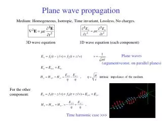
Radio Wave Propagation. VLF ( 3 – 30 KHz) and LF (30 – 300 KHz) Propagation. Introduction. The dominant factor in VLF and LF propagation is the extremely large wavelength of the waves. l ~ 1 – 10 km (VLF) l ~ 0.1 – 1 km (LF)

E N D
Introduction • The dominant factor in VLF and LF propagation is the extremely large wavelength of the waves. • l ~ 1 – 10 km (VLF) • l ~ 0.1 – 1 km (LF) • Because the wavelength is so large, horizontal antennas are not practical (imagine trying to construct a dipole 5km long that is 5km above ground) and only vertical polarization is used. • Although amateurs in the US do not have an LF allocation, some European countries do, at 137 KHz.
Guided Waves • Most VLF and LF propagation occurs via guided wave. • The ground and the ionosphere are highly conductive at this range of frequencies, and they form the “walls” of a spherical waveguide. • Although amateurs in the US do not have an LF allocation, some European countries do, at 137 KHz.
Introduction • The dominant factor in VLF and LF propagation is the extremely large wavelength of the waves. • l ~ 1 – 10 km (VLF) • l ~ 0.1 – 1 km (LF) • Because the wavelength is so large, horizontal antennas are not practical (imagine trying to construct a dipole 5km long that is 5km above ground) and only vertical polarization is used. • Although amateurs in the US do not have an LF allocation, some European countries do, at 137 KHz.
Introduction • The dominant factor in VLF and LF propagation is the extremely large wavelength of the waves. • l ~ 1 – 10 km (VLF) • l ~ 0.1 – 1 km (LF) • Because the wavelength is so large, horizontal antennas are not practical (imagine trying to construct a dipole 5km long that is 5km above ground) and only vertical polarization is used. • Although amateurs in the US do not have an LF allocation, some European countries do, at 137 KHz.
Introduction • The HF region is the one of two regions of RF frequencies that consistently supports long distance propagation.(the other is the VLF/LF/MF) region • The HF region includes: • International broadcasting at on the 120, 90, 60, 49,41,31,25,19,16, and 13 meter bands. • Amateur Radio Service operations on the 80, 40, 30, 20, 17, 15, 12, and 10 meter bands. • Citizens’ Band operation on 11 meters (27 MHz) • Point-to-point military and diplomatic communications
Overview of HF Propagation • Characteristics of HF radio propagation • Propagation is possible over thousands of miles. • It is highly variable. It has daily and seasonal variation, as well as a much longer 11 year cycle. • HF radio waves may travel by any of the following modes: • Ground Wave • Direct Wave (line-of-sight) • Sky Wave
Ground Waves • In the HF region, the ground is a poor conductor and the ground wave is quickly attenuated by ground losses. Some ground wave communication is possible on 80m, but at frequencies above 5 MHz, the ground wave is irrelevant.
Direct Waves • Direct waves follow the line-of-sight path between transmitter and receiver. In order for direct wave communication to occur, antennas at both ends of the path have to have low angles of radiation (so they can “see” each other). This is difficult to do on the lower bands, and as a result, direct wave communication is normally restricted to bands above 20m. Its range is determined by the height of both antennas and generally less than 20 miles.
Sky Waves • Sky waves are waves that leave the transmitting antenna in a straight line and are returned to the earth at a considerable distance by an electrically charged layer known as the ionosphere. Communication is possible throughout much of the day to almost anywhere in the world via sky wave.
The Ionosphere • Created by ionization of the upper atmosphere by the sun. • Electrically active as a result of the ionization. • Bends and attenuates HF radio waves • Above 200 MHz, the ionosphere becomes completely transparent • Creates most propagation phenomena observed at HF, MF, LF and VLF frequencies
The Ionosphere • Consists of 4 highly ionized regions • The D layer at a height of 38 – 55 mi • The E layer at a height of 62 – 75 mi • The F1 layer at a height of 125 –150 mi (winter) and 160 – 180 mi (summer) • The F2 layer at a height of 150 – 180 mi (winter) and 240 – 260 mi (summer) • The density of ionization is greatest in the F layers and least in the D layer
The Ionosphere • Though created by solar radiation, it does not completely disappear shortly after sunset. • The D and E layers disappear very quickly after sunset. • The F1 and F2 layers do not disappear, but merge into a single F layer residing at a distance of 150 – 250 mi above the earth. • Ions recombine much faster at lower altitudes. • Recombination at altitudes of 200 mi is slow slow that the F layer lasts until dawn.
The D-Layer • Extends from 38 – 55 miles’ altitude. • Is created at sunrise, reaches maximum density at noon, and disappears by sunset. • The D layer plays only a negative role in HF communications. • It acts as an attenuator, absorbing the radio signals, rather than returning them to earth. • The absorption is inversely proportional to the square of the frequency, severely restricting communications on the lower HF bands during daylight.
The E layer • Extends from 38 – 55 miles’ altitude. • Is created at sunrise, reaches maximum density at noon, and disappears by sunset. • It can return lower HF frequencies to the Earth, resulting in daytime short skip on the lower HF bands. • It has very little effect on higher frequency HF radio waves, other than to change slightly their direction of travel.
The F Layers • The F1 layer extends from 125 –150 mi (winter) and 160 – 180 mi (summer) • The F2 layer extends from 150 – 180 mi (winter) and 240 260 mi (summer) • The F layers are primarily responsible for long-haul HF communications. • Because there is only F layer ionization throughout the hours of darkness, it is carries almost all nighttime communications over intercontinental distances.
The Critical Frequency (fc) • When radio waves are transmitted straight up towards the ionosphere (vertical incidence), the radio wave will be returned to earth at all frequencies below the critical frequency, (fc) . • The critical frequency depends on the degree of ionization of the ionosphere, as shown in the following equation:
Maximum Usable Frequency (MUF) • Generally, radio waves leave the transmitting antenna at angles of 0 to 30 degrees and hit the ionosphere obliquely, requiring less bending be returned to earth, thus frequencies above the critical frequency can be returned. • The maximum frequency returned at a 0 takeoff angle is called the maximum usable frequency (MUF). The critical frequency and the MUF are related by the following equation: • where R = earth’s radius and h = height of the ionosphere: • Typical MUF values: • 15 – 40 MHz (daytime) • 3 – 14 MHz(nighttime)
Hop Geometry • The longest hop possible on the HF bands is approximately 2500 miles • Longer distances are covered by multiple hop propagation. When the refracted radio wave returns to earth, it is reflected back up towards the ionosphere, which begins another hop.
Daily Propagation Effects • Shortly after sunrise, the D and E layers are formed and the F layer splits into two parts. • The D layer acts as a selective absorber, attenuating low frequency signals, making frequencies below 5 or 6 MHz useless during the day for DX work. • The E and F1 layers increase steadily in intensity from sunrise to noon and then decreases thereafter. • Short skip propagation via the E or F1 layers when the local time at the ionospheric refraction point is approximately noon. • The MUF’s for the E and F1 layers are about 5 and 10 MHz respectively. • The F2 layer is sufficiently ionized to HF radio waves and return them to earth. • For MUF’s is above 5 - 6 MHz, long distance communications are possible. • MUF’s falls below 5 MHz, the frequencies that can be returned by the F layer are completely attenuated by the D layer.
Daily Band Selection • During the daylight hours: • 15, 12, and 10m for multi-hop DX. • 40, 30, 20 and 17m, for short skip. • After dark • 80, 40, 30 and 20m for DX. • Noise levels on 80m can make working across continents very difficult.
Seasonal Propagation Effects • During the winter months, the atmosphere is colder and denser. • The ionosphere moves closer to the earth increasing the electron density. • During the the Northern Hemisphere winter, the earth makes its closest approach to the sun, which increases the intensity of the UV radiation striking the ionosphere. • Electron density during the northern hemisphere winter can be 5 times greater than summer’s. • Winter MUF’s are approximately double summer’s.
Seasonal Band Selection • During Winter: • 20, 17,15, 12, and 10m for daytime DX. • 80, 40, 30 and possible 20m for DX after dark. • During Summer • 20, 17 and 15m for daytime DX. • 40, 30m and 20m after dark.
Geographical Variation • The sun’s ionizing radiation is most intense in the equatorial regions and least intense in the polar regions. • Daytime MUF of the E and F1 layers is highest in the tropics. Polar region MUF’s for these layers can be three times lower. • The F2 layer shows a more complex geographical MUF variation. While equatorial F2 MUF’s are generally higher that polar F2 MUF’s, the highest F2 MUF often occurs somewhere near Japan and the lowest over Scandinavia.
Effects of Sunspots • A sunspot is a cool region on the sun’s surface that resembles a dark blemish on the sun. • The number of sunspots observed on the sun’s surface follows an 11 year cycle. • Sunspots have intense magnetic fields. These fields energize a region of the sun known as the chromosphere, which lies just above the sun’s surface. More ultraviolet radiation is emitted, which increases the electron density in the earth’s atmosphere. • The additional radiation affects primarily the F2 layer. During periods of peak sunspot activity, such as December 2001 or February 1958 the F2 MUF can rise to more than 50 MHz.
Effects of Sunspots • During sunspot maxima, the highly ionized F2 layer acts like a mirror, refracting the higher HF frequencies (above 20 MHz) with almost no loss. • Contacts on the 15, 12 and 10m bands in excess of 10,000 miles can be made using 10 watts or less. • During short summer evenings, the MUF can stay above 14 MHz. The 20 m band stays open to some point in the world around the clock.
Effects of Sunspots • When the sun is very active, it is possible to have backscatter propagation either from the ionosphere or the auroral regions. • Backscatter communication is unique in that the stations in contact do not point their antennas at each other, but instead at the region of high ionization in the ionosphere or towards the north (or south in the other hemisphere) magnetic pole. • During periods of high solar activity, the auroral zone may expand to the south, approaching the US-Canadian border in North America, and covering Scandinavia in Europe.
Effects of Sunspots • During a sunspot minimum, the chromosphere is very quiet and its UV emissions are very low. • F2 MUF’s decrease, rarely rising to 20 MHz • Most long distance communications must be carried out on the lower HF bands. • During periods of high sunspot activity: • The best daytime bands are 12 and 10m. • At night, the best bands are 20, 17 and 15m. • At the low end of the solar cycle, • The best daytime bands are 30 and 20m. • After dark, 40m will open for at least the early part of the evening. • In the early morning hours, only 80m will support worldwide communications
Propagation Disturbances • A solar flare is a plume of very hot gas ejected from the sun’s surface. • It rises through the chromosphere into the corona, disturbing both regions. • X-ray emission from the corona increases, which reaches Earth in less than 9 minutes. If they are intense enough, the ionosphere will become so dense that all HF signals are absorbed by it and worldwide HF communications are blacked out. • Large numbers of charged particles are thrown out into space at high velocity, reaching Earth in 2-3 days. The particles are deflected by the geomagnetic field to the poles, expanding the auroral zones. Signals traveling through the auroral zone are severely distorted, in some cases to the point of unintelligibility • Generally speaking, ionospheric disturbances affect the lowest HF bands most. Occasionally communications on 10m may be possible
Propagation Indices • K index – a local index of geomagnetic activity computed every three hours at a variety of points on Earth. The K scale is shown below. • The best HF propagation occurs when K is less than 5. A K index less than 3 is usually a good indicator of quiet conditions on 80 and 40m.
Propagation Indices • Ap index - a daily average planetary geomagnetic activity index based on local K indices. The A scale is shown below: • Good HF propagation is likely when A is less than 15, particularly on the lower HF bands. When A exceeds 50 , ionospheric backscatter propagation is possible on 12 and 10m. When A exceeds 100, auroral backscatter may be possible on 10m.
Propagation Indices • The K and Ap indices are related as follows:
Propagation Indices • Solar Flux – This index is a measure of 10.7 cm microwave energy emitted by the sun. A flux of 63.75 corresponds to a spot free, quiet sun. As the flux number increases, the solar activity increases. Single hop HF propagation is normally possible on bands below 20m when the flux is greater than 70. Multi-hop propagation is possible on 80 – 20m when the flux exceeds 120. Openings on 15 and 10 meters are common when the flux exceeds 180. Should the flux exceed 230, multi-hop propagation is possible up into the VHF region.
Propagation Indices • Sunspot Number (Wolf Number)– This is the oldest measure of sunspot activity, with continuous records stretching back into the 19th century. The sunspot number is computed multiplying the number of sunspot groups observed by 10 and adding this to the number of individual spots observed. Because the sun rotates and different areas of the sun are visible each day, it is common to use 90 day or annual average sunspot numbers. The lowest possible sunspot number is 0. The largest annual average value recorded to date was 190.2 in 1957. As with solar flux, higher sunspot numbers equate to more solar activity.
Propagation Indices Solar Flux and Sunspot Number for the past 15 years (September 1986 – March 2002):
Propagation Indices This chart shows the solar flux for the past 15 years (September 1986 – March 2002):
VHF Propagation Modes • Every type of propagation is possible in the VHF range: • Line of Sight (LOS) • Tropospheric Propagation (tropo) • Sporadic E • Meteor Scatter • Auroral Scattering • Transequatorial F • Ionospheric F2 • LOS and tropo occur throughout the VHF range, while the other modes are most frequently observed below 150 MHz
Line of Sight (LOS) and Tropospheric Propagation • Line of Sight • LOS coverage is determined primarily by the height of the transmitting and receiving antennas • For typical amateur 6 m stations LOS coverage is about 20 miles • LOS propagation is unaffected by solar conditions, time of day or the seasons • Tropospheric Propagation • Variations in the humidity of the troposphere cause RF to be scattered over the horizon. This is known as tropospheric scatter • Temperature inversions (warm dry air located above cool moist air) refract RF in the VHF range back towards the earth. Temperature inversions occur daily in the middle latitudes at sunrise and sunset. Communications are possible over a ranges up to 600 miles • Over the oceans, stable temperature inversions can create a duct, through which VHF can travel without significant loss up to 2500 miles
Tropospheric Scatter Tropospheric Ducting
Sporadic E (ES) • Clouds of high density ionization form without warning in the ionosphere’s E layer • ES is not dependent on solar activity. It may occur any time, but is most frequent between May and August, with a smaller peak of activity in December • Single hop ES has a range of ~1400 mi • Double hop ES has a range of ~ 2500 mi • Cause of Sporadic E is not known: high altitude wind shear may be responsible.
Sporadic E (ES) The ionized clouds that cause sporadic E propagation can move. This animated sequence shows grid squares contacted in ½ hour intervals during an ES opening beginning at 0500 Z, 10 June 2001
Meteor Scatter • As meteors are vaporized in the upper atmosphere, they leave behind ionized trails at heights of 60 – 70 miles that are sufficiently dense to reflect VHF • A long trail lasts only 15 seconds so contact must be made quickly on SSB • SSB QSO’s via meteor scatter are usually possible only during a meteor storm • Short trails that occur continuously may be used for high speed CW QSO’s (> 100 wpm) • Best time for meteor scatter is after midnight or during a meteor storm
Aurora (Au) • During periods of intense auroral activity, charged particles in the auroral zone can scatter 50 MHz RF • The RF interacts strongly with the aurora, resulting in significant distortion of the signal. Only narrow band modes such as CW are used during Au openings • To work Au, the transmitter and receiver point their antennas at the auroral zone, not each other.