Download
1 / 11
110 likes | 229 Vues
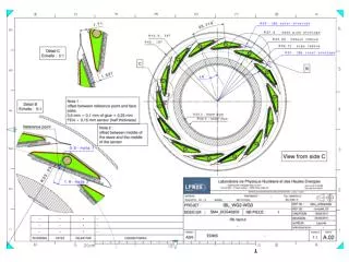
IBL TYPE 01 CABLES AND INTERMEDIATE FLEXES. IBL PACKAGE OVERVIEW. Sealing ring. Staves. iFlexes. Type 01 bundles. IP=0mm. End of stave : 377 mm. iFlexes : 693 mm. IPT service ring 01: 912 mm. IPT service ring 02: 1423 mm. IPT service ring 03: 1984 mm.

E N D
IBL PACKAGE OVERVIEW Sealing ring Staves iFlexes Type 01 bundles IP=0mm End of stave: 377 mm iFlexes: 693 mm IPT service ring 01: 912 mm IPT service ring 02: 1423 mm IPT service ring 03: 1984 mm IPT service ring 04: 2544 mm IPT service ring 05: 3250 mm End of IPT: 3386 mm
SERVICES INSIDE IBL PACKAGE IPT SERVICE RING 1 + Z STOPPER IPT SERVICE RING 2 IPT SERVICE RING 5 + Z STOPPER PP1 IP IPT SERVICE RING 3 IPT SERVICE RING 4 STAVES iFlexes IPT SERVICE RING 1+ Z STOPPER
iFlex test setup • iFlex stiffness setup goal: force vs displacement • In nominal position with respect to CAD, the resulting force is 4.5 N: • Need to guaranty the final shape of the iFlex or set up the nominal iFlex positioning at 0 N force with final material. • Need to strain relieve the PP0 area to assure a safe mating of connectors
Bundle z stopper • Prototypes in production for testing onto the thermal mockup (see mockup team presentation) • Design made according to last bundle dimensions sent by SLAC (Ø7.5 mm at cable board exit). • Dot of glue for pipe • Potting for bundle Ø8
TYPE01 BUNDLE • Nominal length between cable board and potting is 2452 mm. • We added 7 mm additional length for: • Thermal contraction (3mm) • Manufacturing tolerances (+-1mm) • Installation clearance • CAD and thermal mockup shows that 7 mm is the maximum overlength that we can integrate without compromising the integration
TYPE01 BUNDLE MANDATORY KEY POINTS • The distance between the cable board and the potting must be precise: • Not enough overlength in cold phase if too short • Integration problem if too long • LAPP requested two different lengths for the power bundles and a diminution of the data bundle length for wrapping issue
TYPE01 BUNDLE MANDATORY KEY POINTS • The two bundles after exiting the potting at PP1 must only be covered with shielding braid: • EMI connection • Integration issue on IPT extremity ring • LAPP test shows that a 6 mm bundle can fit Power bundle data bundle Cooling fitting
TYPE01 BUNDLE MANDATORY KEY POINTS • NTC sensor location: • Modeling according to E.VIGELOAS tests at CPPM • Bonded on the sleeve • What is the connection location on CB and the number of sensors to implement ? NTC sensor
CONCLUSION • The iFlex must be manufactured with respect to drawing in order to avoid critical stresses in the PP0 area and a possible de-mating. • The overlength between the cable board and the PP1 potting is critical for integration and should be precisely checked. This is also the case for the location of the Z stoppers during the potting stage. • The potting and bundles diameters are mandatory for an efficient seal and allow the bundle integration in the IBL package. • The length of the data and the power bundle must be respected to make the wrapping on the BP extender.