Download

1 / 52
520 likes | 692 Vues
A Tissue Engineered Bioactive Vascular Scaffold. Karen Roberts – Biomedical Engineering Janell Carter – Biomedical Engineering Dr. Kenneth Barbee – Advisor Senior Design Final Presentation May 24, 2001. Objective. The broad objective is to develop a bioactive vascular scaffold

E N D
A Tissue Engineered Bioactive Vascular Scaffold Karen Roberts – Biomedical Engineering Janell Carter – Biomedical Engineering Dr. Kenneth Barbee – Advisor Senior Design Final Presentation May 24, 2001
Objective The broad objective is to develop a bioactive vascular scaffold Specific Scaffold Geometry Mechanical Conditioning Dynamic Culturing
Proposed Tissue Engineered Artery A tissue engineered biodegradable PLAGA electrospun cylindrical scaffold seeded with smooth muscle cells The electrospun scaffold will provide a porous environment for cell invasion The mechanical properties will be enhanced with dynamic mechanical conditioning
Significance Solutions Available Our Proposed Idea Electrospinning Dynamic Mechanical Conditioning Phase I Phase II Results Problems Encounted Future Investigations – Phase III References Agenda
Significance Cardio vascular disease is principle killer in US About 58 million American (almost one-fourth of the nations population) live with some form of cardiovascular disease • High blood pressure - 50,000,000 • Coronary heart disease - 12,200,000 Small Artery Graft procedures - 600,000/ yr
Solutions Available • Angioplasty • Balloon catheter • Stent • Small mesh like wire tube • 95% successful • 20-25% experience restenosis • Bypass • Segment of vein, usually from leg, to by pass blockage.
Implants & Solution In Development • Endothelial Cell Repair • Endothelial cell / polymer matrix scaffold • Help fight restenosis • Collateral angiogenesis • Burning tiny holes into heart for vessel growth • Hormone therapy
Pseudo Tissue Engineered Arteries • Plastic tube surgically placed in abdominal cavity • Fibrous tissue growth • Tube removed, tissue tube used for bypass • Animal studies have lasted 12 months
Background Ideally – Tissue engineering is to develop a material that is biologically functional Synthetic material results in heightened immune response Bioabsorbable scaffold would guide cells to a specific geometry and degrade as the cells proliferate
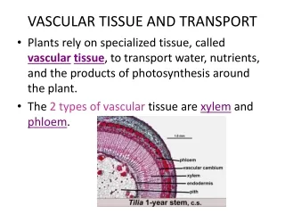
Anatomy Tunica Intima Elastic = Mixed = Muscular Tunica Media • Elastic: greater elastin-collagen content • Mixed: Equal SMC and elastin-collagen content • Muscular: greater SMC content Tunica Adventia Elastic = Mixed = Muscular
Anatomy – Tunica Media • The number of concentric layers is proportional to wall thickness Aorta – Thin Wall relative to internal diameter Coronary – Thick walled relative to diameter • Surrounding elastic lamina is less defined in comparison with the internal lamina
Mechanical Properties • Visco-elastic Stress-Strain Curve • Two moduli shows both properties • Coronary arteries are in most demand • Physiological pressures • Systolic 120 mmHg • Diastolic 90 mmHg
Dynamic Mechanical Conditioning Repetitive mechanical conditioning in the form of cyclic stress Inflation and deflation of silicone conduits in a bioreactor by filling with cell culturing medium This is hypothesized to increase cell growth, proliferation, and enhance organization – As a result mechanical properties will be enhanced Studies by Seliktar et al. have had moderate success
PLAGA Components – Lactic Acid and Glycolic Acid Glycolic acid is naturally occurring in fruit acid derived from sugar cane Lactic acid is a naturally occurring substance found in body They form a copolymer when polymerized Dexon was first FDA approved totally synthetic absorbable suture
PLAGA Copolymer degrades by hydrolysis Macrophages easily consume these particles Mechanical properties can be altered by changing the concentrations and chain lengths Homopolymer combinations are more crystalline Copolymers are more amorphous
Electrospinning A nonwoven porous mesh can be fabricated by electrospinning The electrospinning process employs the use of electrostatic fields to form and accelerate liquid jets from the tip of a capillary Evaporation of the solvent forms fibers that are nanometers in diameter The resultant nonwoven mesh is of variable fiber diameters and pore size distribution
Tensile test Young’s modulus % Elongation Toughness Ultimate strength Porosity Average Pore Size SEM Mat thickness Porosity Fiber diameter Matrix Characterization
Mechanical Testing Used to determine the stress/ strain data under tension, compression, and torsion Nanofiber matrices - tensile test are conducted because the primary force arteries are subjected to in vivo are radial tensile forces There is an acceptable amount of error associated with this data
Specific Aims – Phase I Electrospin a variety of mats in accordance to our design matrix Fully characterize the mats by performing mechanical and porosity tests
Specific Aims – Phase II Electrospin PLAGA scaffold on to a mandrel of characteristic artery shape according to results from phase I Conduct characterization by SEM
Specific Aims – Phase III Sterilization of scaffolds Seed smooth muscle cells on to cylindrical scaffold Dynamically culture cells and mechanically condition scaffold. PLAGA degredation studies
Goals Achieved Phase I: 20 wt% PLAGA Planar Mat Phase II: Cylindrical PLAGA Scaffolds 15 wt % - 20 wt% - 25 wt% 20 wt% - 25 wt% layered
Preliminary Study Procedure Electrospun mat from 20 wt % PLAGA in 80:20 THF/DMF solution Characterization • Tensile testing – 1x6 cm strips • SEM – 1cm2 gold sputtered • Porosity – Mercury fills pores for density readings
Secondary Study Procedure The primary goal of this study was to achieve a variety electrospun 50:50 PLAGA scaffold in a tubular shape • 15 wt% • 20 wt% • 25 wt% • Layered 20 & 25 wt% Characterization of cylindrical scaffold • SEM – 1cm2 gold sputtered
Rotation Device Polymer solution Grounded aluminum mandrel Grounded aluminum mandrel Positive needle Silicone mandrel
Construct Aluminum Mandrel Silicone Sleeve A silicone sleeve slid over a grounded aluminum mandrel The construct was attached to a gearbox with a motor Construct was rotated at a gear ratio of 807.93:1 PLAGA Construct
Results Preliminary Study: • 20 wt% PLAGA Planar Mat
20 wt% PLAGA Planar Mat Fiber Diameter: 170 nm – 10 mm Pore Size: 1-100 mm
Results Secondary Study: Cylindrical PLAGA Scaffolds • 15 wt % • 20 wt% • 25 wt% • 20 wt% - 25 wt% layered
15 wt% PLAGA Cross Section Thickness: 241mm Fiber Diameter: None Pore size None
20 wt % PLAGA Cross Section Thickness: 15 mm Fiber Diameter: 170 nm Pore Size: 1 – 5 mm
25 wt % PLAGA Cross Section Thickness: 60 mm Fiber Diameter: 1-10 mm Pore Size: 10 – 50 mm
25 wt% PLAGA Cross Section Thickness: 60 mm Fiber Diameter: 1-10 mm Pore Size: 10 – 50 mm
25 wt % PLAGA Lateral View Thickness: 60 mm Fiber Diameter: 1-10 mm Pore Size: 10 – 50 mm
20 wt% & 25 wt% PLAGA Layered Lateral View Thickness Total: 108 mm Thickness Each Layer: 34 mm 38 mm 34 mm 36 mm
20 wt% & 25 wt% PLAGA Layered Cross Section Thickness Total: 108 mm Thickness Each Layer: 34 mm 38 mm 34 mm 36 mm
Phase I & II– Humidity/Rain – Properties of Electrospun PLAGA was compromised in these conditions i.e. melting Phase III – Sterilization – All forms of sterilization melted the PLAGA except UV radiation & ethylene oxide UV radiation – Did not completely sterilize all of the time Money – dynamic culturing apparatus upwards of $40K Problems Encountered
Future Investigations – Phase III The scaffold that we designed was for use with Dynatek Dalta SVP216 - Small Vascular Prosthesis Tester This would provide the environment for dynamic mechanical conditioning of the cell seeded scaffold while maintaining an environment that is suitable for cell growth & proliferation
Cell Culturing Seeding cells and incubate for 2 days using standard cell culturing techniques This is to allow for cell adhesion to PLAGA Dynamically condition / culturing for 4 – 8 additional days
SVP216 - Small Vascular Prosthesis Tester Produce data acceptable to the FDA Positive displacement pumping system ensures known geometric expansion of samples All samples submersible in 37 degree C bath 2mm-16mm inner diameter grafts
Latex and Silicone Precision Mock Arteries Known mechanical properties leaves no second guessing Get the exact fit with precision diameters Fit all your products with virtually any shape or size
Considerations for the Future Mechanical conditioning must maintaining the correct mechanical properties – Smooth muscle cells will rearrange within the scaffold as mechanical conditioning occurs Liquid Chromatography / Mass Spectroscopy monitoring of degradation of the polymer matrix over time A variety of PLAGA mixtures such as 85:15 or 90:10
Dr. Kenneth Barbee Dr. Frank Ko Dr. Attawia Yusef Khan – Porosity Asaf Ali – Mechanical Testing Dave Rohr – SEM Special Thanks