Download
1 / 18
180 likes | 360 Vues
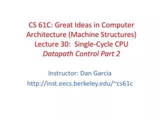
Machine Structures Lecture 19 – CPU Design: Designing a Single-cycle CPU, pt 2. Halloween plans? Try the Castro, SF!. Tomorrow 2005-10-31, runs until 11pm …go at least once…. halloweeninthecastro.com. Happy Halloween, everyone!. How to Design a Processor: step-by-step.

E N D
Machine StructuresLecture 19 – CPU Design: Designing a Single-cycle CPU, pt 2 Halloween plans?Try the Castro, SF! Tomorrow 2005-10-31,runs until 11pm …go at least once… halloweeninthecastro.com Happy Halloween, everyone!
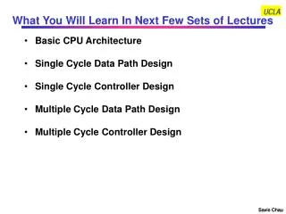
How to Design a Processor: step-by-step 1. Analyze instruction set architecture (ISA) => datapath requirements • meaning of each instruction is given by the register transfers • datapath must include storage element for ISA registers • datapath must support each register transfer 2. Select set of datapath components and establish clocking methodology 3. Assemble datapath meeting requirements 4. Analyze implementation of each instruction to determine setting of control points that effects the register transfer. 5. Assemble the control logic
Step 3: Assemble DataPath meeting requirements • Register Transfer Requirements Datapath Assembly • Instruction Fetch • Read Operands and Execute Operation
Next Address Logic Address Instruction Memory 3a: Overview of the Instruction Fetch Unit • The common RTL operations • Fetch the Instruction: mem[PC] • Update the program counter: • Sequential Code: PC PC + 4 • Branch and Jump: PC “something else” clk PC Instruction Word 32
3b: Add & Subtract • R[rd] = R[rs] op R[rt] Ex.: addU rd,rs,rt • Ra, Rb, and Rw come from instruction’s Rs, Rt, and Rd fields • ALUctr and RegWr: control logic after decoding the instruction 31 26 21 16 11 6 0 op rs rt rd shamt funct 6 bits 5 bits 5 bits 5 bits 5 bits 6 bits Rd Rs Rt ALUctr RegWr 5 5 5 busA Rw Ra Rb busW 32 Result 32 32-bit Registers ALU 32 32 busB clk 32 Already defined the register file & ALU
Clocking Methodology Clk • 存储单元由同样的边缘定时 • 物理设备, flip-flops (FF)和组合逻辑会有一些延时 • 门电路: 输入引起输出变化之间有延时 • 在FF D输入端的信号必须稳定,然后,激发时钟边缘才允许信号FF (set-up time)中通过, 因此这里也会有clock-to-Q延时 • “关键路径Critical path” (通过逻辑电路的最长路径) 确定时钟周期的长度 . . . . . . . . . . . .
ALU Register-Register Timing: One complete cycle Clk New Value Old Value PC Instruction Memory Access Time Rs, Rt, Rd, Op, Func Old Value New Value Delay through Control Logic ALUctr Old Value New Value RegWr Old Value New Value Register File Access Time busA, B Old Value New Value ALU Delay busW Old Value New Value ALUctr RegWr Rd Rs Rt Register Write Occurs Here 5 5 5 busA 32 Rw Ra Rb busW 32 RegFile busB 32 clk
op rs rt 31 16 15 0 immediate 0 0 0 0 0 0 0 0 0 0 0 0 0 0 0 0 16 bits 16 bits ALU 3c: Logical Operations with Immediate • R[rt] = R[rs] op ZeroExt[imm16] ] 31 26 21 16 0 immediate 6 bits 5 bits 5 bits 16 bits ALUctr RegWr Rd Rs Rt 5 5 5 busA 32 Rw Ra Rb busW 32 RegFile busB 32 clk
op rs rt 31 16 15 0 immediate 0 0 0 0 0 0 0 0 0 0 0 0 0 0 0 0 16 bits 16 bits ALU 3c: Logical Operations with Immediate • R[rt] = R[rs] op ZeroExt[imm16] ] 31 26 21 16 0 immediate 6 bits 5 bits 5 bits 16 bits RegDst Rd Rt What about Rt register read?? 1 0 RegWr Rs Rt ALUctr 5 5 5 busA 32 Rw Ra Rb 32 RegFile busB 32 0 32 clk imm16 1 ZeroExt 16 32 ALUSrc • Already defined 32-bit MUX; Zero Ext?
31 26 21 16 0 op rs rt immediate 6 bits 5 bits 5 bits 16 bits ALU 3d: Load Operations • R[rt] = Mem[R[rs] + SignExt[imm16]] Example: lw rt,rs,imm16 RegDst Rd Rt 1 0 RegWr Rs Rt ALUctr 5 5 5 busA 32 Rw Ra Rb 32 RegFile busB 32 0 32 clk imm16 1 ZeroExt 16 32 ALUSrc
31 26 21 16 0 op rs rt immediate 6 bits 5 bits 5 bits 16 bits 1 0 ALU 0 1 3d: Load Operations • R[rt] = Mem[R[rs] + SignExt[imm16]] Example: lw rt,rs,imm16 MemtoReg ALUctr RegDst Rd Rt MemWr RegWr Rs Rt 5 5 5 busA 32 Rw Ra Rb busW 32 RegFile busB 32 0 32 clk ? 32 WrEn Adr imm16 Data In 1 Extender Data Memory 16 32 clk ALUSrc ExtOp
31 26 21 16 0 op rs rt immediate 6 bits 5 bits 5 bits 16 bits 1 0 ALU 0 1 3e: Store Operations • Mem[ R[rs] + SignExt[imm16] ] = R[rt] Ex.: sw rt, rs, imm16 MemtoReg ALUctr RegDst Rd Rt MemWr RegWr Rs Rt 5 5 5 busA 32 Rw Ra Rb busW 32 RegFile busB 32 0 32 clk 32 WrEn Adr imm16 Data In 1 Extender Data Memory 16 32 clk ALUSrc ExtOp
31 26 21 16 0 op rs rt immediate 6 bits 5 bits 5 bits 16 bits 1 0 ALU 0 1 3e: Store Operations • Mem[ R[rs] + SignExt[imm16] ] = R[rt] Ex.: sw rt, rs, imm16 MemtoReg ALUctr RegDst Rd Rt MemWr RegWr Rs Rt 5 5 5 busA 32 Rw Ra Rb busW 32 RegFile busB 32 0 32 clk 32 WrEn Adr imm16 Data In 1 Extender Data Memory 16 32 clk ALUSrc ExtOp
31 26 21 16 0 op rs rt immediate 6 bits 5 bits 5 bits 16 bits 3f: The Branch Instruction beq rs, rt, imm16 • mem[PC] Fetch the instruction from memory • Equal = R[rs] == R[rt] Calculate branch condition • if (Equal) Calculate the next instruction’s address • PC = PC + 4 + ( SignExt(imm16) x 4 ) else • PC = PC + 4
31 26 21 16 0 op rs rt immediate 6 bits 5 bits 5 bits 16 bits 00 PC Datapath for Branch Operations • beq rs, rt, imm16 Datapath generates condition (equal) Inst Address Equal nPC_sel 4 ALUctr RegWr Rs Rt Adder 5 5 5 busA 32 Rw Ra Rb = busW 32 Mux RegFile ALU busB Adder 32 clk clk PC Ext Already have mux, adder, need special sign extender for PC, need equal compare (sub?) imm16
Inst Memory Adr Adder Adder Mux 1 0 = 00 ALU 0 PC 0 WrEn Adr 1 1 Extender Data Memory PC Ext Putting it All Together:A Single Cycle Datapath Instruction<31:0> <0:15> <21:25> <16:20> <11:15> Rs Rt Rd Imm16 RegDst nPC_sel MemtoReg ALUctr Rd Rt Equal MemWr RegWr Rs Rt 4 5 5 5 busA 32 Rw Ra Rb busW 32 RegFile busB 32 32 clk 32 clk imm16 Data In 16 32 clk imm16 ExtOp ALUSrc
ALU An Abstract View of the Implementation Control Ideal Instruction Memory Control Signals Conditions Instruction Rd Rs Rt 5 5 5 Instruction Address A Data Addr Data Out Rw Ra Rb 32 32 Ideal Data Memory 32 Register File PC Next Address B Data In clk clk clk 32 Datapath
Summary: Single cycle datapath • 5 steps to design a processor • 1. Analyze instruction set => datapath requirements • 2. Select set of datapath components & establish clock methodology • 3. Assemble datapath meeting the requirements • 4. Analyze implementation of each instruction to determine setting of control points that effects the register transfer. • 5. Assemble the control logic • Next time! Processor Input Control Memory Datapath Output