Download
1 / 43
430 likes | 546 Vues
Group IV Stephen Nichols Jason Lambert Rafael Enriquez. Vacuum Tube amplifier. Stephen.

E N D
Group IV Stephen Nichols Jason Lambert Rafael Enriquez Vacuum Tube amplifier
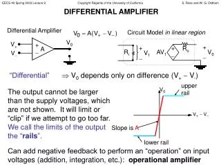
Stephen A Vacuum tube audio amplifier for which the entire signal path is analog but the audio parameters are digitally controlled via a touch screen graphical user interface which also displays visualizations of the amplitude, frequency and phase characteristics of the audio signals. description
Stephen • Our project will be embody the analog aspects of modern commercial VTAs such as this one. • The unique feature of our project is digital controlled source switching, volume, and graphic equalizer with a touch screen, LCD to display music visualizations. • As far as we can determine, no other modern VTA has this feature. motivation JE-Audio, model VM60 This unit is about 5” x 13” x 16” weighs about 45 pounds and costs about $6300 per pair. Image reprinted with permission from John Lam of JE-Audio
Jason goals CONTROL PANEL POSSIBLE MUSIC VISUALIZATIONS
Stephen Hardware requirements
Stephen INTERNAL DETAIL (TOP VIEW) Input and Output Jacks Fan (if needed) AC Power Terminal Strip Speaker Relay Low Voltage Transformer High Voltage Power Supply Microcontroller, Low Voltage Power Supply, Optocouplers LCD / Touchscreen Right Audio Processor CCA Left Audio Processor CCA
SOURCES LOCAL VOLT REG B SPEAKER TO ALL AUDIO STAGES PHONO RIAA EQU INPUT SOURCESELECT GRAPHIC EQUAL-IZER TUBE PREAMP AND PHASE SPLITTER TUBE PUSH- PULL AMP Z- MATCH XFMR TAPE PRE-EQU GAIN ADJ BUFF BUFF VOL ADJ INPUTS TUNER AUX GAIN SEL IN BUFFER HIGH VOLT SUPPLY A VR1 VR2 VR3 VR4 DIGITAL POTENTIOMETERS VR5 A B VR6 VR7 110 VOLTS AC VR8 MICROCONTROLLER OPTO COUPLERS LOW VOLT SUPPLY 16 MILLION COLOR 800 x 480LIQUID CRYSTALDISPLAY CLOCK OSC TOUCHSCREEN EXTERNAL USB PROGRAM INTERFACE
Stephen AUDIO INPUT BLOCK DIAGRAM SOURCES LOCAL VOLT REG B SPEAKER TO ALL AUDIO STAGES PHONO RIAA EQU INPUT SOURCESELECT GRAPHIC EQUAL-IZER TUBE PREAMP AND PHASE SPLITTER TUBE PUSH- PULL AMP Z- MATCH XFMR TAPE PRE-EQU GAIN ADJ BUFF BUFF VOL ADJ INPUTS TUNER AUX GAIN SEL IN BUFFER HIGH VOLT SUPPLY A VR1 VR2 VR3 VR4 DIGITAL POTENTIOMETERS VR5 A B VR6 VR7 110 VOLTS AC VR8 MICROCONTROLLER OPTO COUPLERS LOW VOLT SUPPLY 16 MILLION COLOR 800 x 480LIQUID CRYSTALDISPLAY CLOCK OSC TOUCHSCREEN EXTERNAL USB PROGRAM INTERFACE AUDIO PATH FOR ONE CHANNEL SHOWN ONLY – THE OTHER IS SIMILAR
Stephen AUDIO INPUT SCHEMATIC From low-voltage power supply To graphic equalizer From back panel input jacks (not shown) From MCU
Stephen The analog multiplexer, driven by two GPIOs from the MCU, selects one of four input sources. The output of the multiplexer is buffered by a unity-gain stage to provide a constant-impedance drive for the equalizer stage. One VR channel is used to equalize the levels of the various signals (see chart) and is set to a pre-determined value by the MCU as the sources are selected. AUDIO INPUT PROCESSING
Stephen Op-amps: The important parameters are: Noise voltage, THD, Price, availability in a DIP, and model support in NI Multisim. The Texas Instruments LM4562 was an obvious choice for all analog processing up to the vacuum tube stages. Analog Multiplexer: Four AC input sources to be selectable with the highest isolation between channels available in DIP. The physical implementation is two identical CCAs so a dual-channel switch was not considered. Four candidate parts were considered (see table); the final choice was the ADG408. AUDIO INPUT DESIGN DECISIONS The ADG408BN was chosen due to excellent crosstalk, compatibility with the power supply voltages and performance during simulation
Jason GRAPHIC EQUALIZER SOURCES LOCAL VOLT REG B SPEAKER TO ALL AUDIO STAGES PHONO RIAA EQU INPUT SOURCESELECT GRAPHIC EQUAL-IZER TUBE PREAMP AND PHASE SPLITTER TUBE PUSH- PULL AMP Z- MATCH XFMR TAPE PRE-EQU GAIN ADJ BUFF BUFF VOL ADJ INPUTS TUNER AUX GAIN SEL IN BUFFER HIGH VOLT SUPPLY A VR1 VR2 VR3 VR4 DIGITAL POTENTIOMETERS VR5 A B VR6 VR7 110 VOLTS AC VR8 MICROCONTROLLER OPTO COUPLERS LOW VOLT SUPPLY 16 MILLION COLOR 800 x 480LIQUID CRYSTALDISPLAY CLOCK OSC TOUCHSCREEN EXTERNAL USB PROGRAM INTERFACE AUDIO PATH FOR ONE CHANNEL SHOWN ONLY – THE OTHER IS SIMILAR
Jason Graphic equalizer • DESIGN DECISIONS
Jason GRAPHIC EQUALIZER
Jason GRAPHIC EQUALIZER
Jason Digital Potentiometers • DESIGN DECISIONs
Jason Digital potentiometers • difficulties A loading effect occurred on the data lines which caused the serial data input to the digital potentiometers to possibility change during the data hold time.
Stephen VTA BLOCK DIAGRAM SOURCES LOCAL VOLT REG B SPEAKER TO ALL AUDIO STAGES PHONO RIAA EQU INPUT SOURCESELECT GRAPHIC EQUAL-IZER TUBE PREAMP AND PHASE SPLITTER TUBE PUSH- PULL AMP Z- MATCH XFMR TAPE PRE-EQU GAIN ADJ BUFF BUFF VOL ADJ INPUTS TUNER AUX GAIN SEL IN BUFFER HIGH VOLT SUPPLY A VR1 VR2 VR3 VR4 DIGITAL POTENTIOMETERS VR5 A B VR6 VR7 110 VOLTS AC VR8 MICROCONTROLLER OPTO COUPLERS LOW VOLT SUPPLY 16 MILLION COLOR 800 x 480LIQUID CRYSTALDISPLAY CLOCK OSC TOUCHSCREEN EXTERNAL USB PROGRAM INTERFACE AUDIO PATH FOR ONE CHANNEL SHOWN ONLY – THE OTHER IS SIMILAR
Stephen VTA SCHEMATIC From graphic equalizer To speaker, via relay (not shown) 5 Volts AC for tube heaters From High Voltage Power Supply
Stephen Four candidate architectures were investigated early in the project to select the design approach of the power amplifier: Single-ended and push-pull configurations and with or without global feedback, see table. Design 1 was chosen as offering the best frequency response and highest power at the lowest distortion. VTA ARCHITECTURE selection
Stephen VTAs are favored by many musicians and high-end audio enthusiasts for their mellower sound and low-distortion characteristics. This effect, known as “tube sound”, is believed to come from the “soft clipping” characteristics of vacuum tube amplifiers which emphasize even-order harmonics, as opposed to solid-state designs that tend to produce odd-order harmonics when they sharply clip during musical peaks. During the architecture selection, the distortion characteristics of the various configurations were analyzed with NI Multisim. In general, the even-order harmonics tended to be of higher amplitude than the next odd-order harmonic (see Table1). Note that even-order harmonics are simply the same musical note at a higher octave (see Table 2) VTA DISTORTION Table 1 Table 2 (Music notes are per the Equal Tempered Chromatic Scale)
Stephen V3 is a dual-triode tube configured as a phase splitter. Various reference designs used type 12xx7 tubes so several were analyzed in NI Multisim. The type 12BH7A was chosen due to slightly lower THD characteristics V2 and V1 are beam power pentode tubes configured as a push-pull amplifier with a center-tapped transformer as their plate load. Type 6L6 tubes were chosen due to almost universal use in reference designs. Impedance Transformer: The model 125E was chosen due to being specifically designed for this application, flexible impedance ratio and availability. It provides six taps on the secondary ranging from 3KΩ to 22.5KΩ. A value of 5.6KΩ ohms was chosen because it provided the best combination of maximum output power and THD. VTA DESIGN decisions
Stephen • The optimal configuration of the push-pull amplifier was challenging due to several conflicting factors: • Maximum output power occurs with the highest plate voltage. High plate voltages unfortunately run the risk of exceeding the 6L6 maximum plate voltage rating of 500 volts. • Lowest distortion was achieved with lower values of cathode resistor, however this resulted in higher plate voltages. Audio processor difficulties
Stephen The audio input circuits, analog multiplexer and graphic equalizer were prototyped and worked. A few minor schematic issues were discovered during this process, which have been resolved. Audio processor successes
Stephen HV POWER SUPPLY BLOCK DIAGRAM SOURCES LOCAL VOLT REG B SPEAKER TO ALL AUDIO STAGES PHONO RIAA EQU INPUT SOURCESELECT GRAPHIC EQUAL-IZER TUBE PREAMP AND PHASE SPLITTER TUBE PUSH- PULL AMP Z- MATCH XFMR TAPE PRE-EQU GAIN ADJ BUFF BUFF VOL ADJ INPUTS TUNER AUX GAIN SEL IN BUFFER HIGH VOLT SUPPLY A VR1 VR2 VR3 VR4 DIGITAL POTENTIOMETERS VR5 A B VR6 VR7 110 VOLTS AC VR8 MICROCONTROLLER OPTO COUPLERS LOW VOLT SUPPLY 16 MILLION COLOR 800 x 480LIQUID CRYSTALDISPLAY CLOCK OSC TOUCHSCREEN EXTERNAL USB PROGRAM INTERFACE AUDIO PATH FOR ONE CHANNEL SHOWN ONLY – THE OTHER IS SIMILAR
Stephen HIGH VOLTAGE POWER SUPPLY 450 Volts DC to the VTA 360 Volts AC from a transformer Room provided on the circuit board, if required
Rafa Low voltage power supply difficulties
Rafa Low voltage power supply Before receiving display panel
Rafa Low voltage power supply difficulties • Resistor values had to be changed to match standard values.
Rafa Low voltage power supply success
Jason • For simplicity we decided to go with a monolithicmicrocontroller design instead of multiply low performance controllers. • Eliminates the need for inter micro controller communication bus • Simpler hardware footprint • Easier to synchronize multiple interrupts Microcontroller topology • Design decisions
Jason Microcontroller selection • Design decisions
Rafa display requirements
Rafa display options
Rafa display decision
Rafa display difficulties
Rafa display successes
Digital Equalizer Visualization State Detector EQ Sound Analyzer Values Updater Set mode Graphics Generator I Graphics Generator II Graphics Update Rafa Display Software diagram
Rafa Immediate plan for completion
Stephen AUDIO PROCESSOR Plan for completion
Rafa Current progress
Stephen This project is self-funded by the group, with Stephen providing 90% of the funds The original budget of this project was $500 As of now, approximately $500 has been spent The following costs remain: OVERALL Budget & financing details