Download
1 / 36
490 likes | 1.02k Vues
LOW TEMPERATURE PHOTONIC SINTERING FOR PRINTED ELECTRONICS. Saad Ahmed, Ph.D. Engineering Manager Xenon Corporation ICFPE Japan September 8, 2012. Topics. Introduction to Pulsed Light Photonic Sintering for Printed Electronics Sintering Different Materials Silver Copper Gold

E N D
LOW TEMPERATURE PHOTONIC SINTERING FOR PRINTED ELECTRONICS Saad Ahmed, Ph.D. Engineering Manager Xenon Corporation ICFPE Japan September 8, 2012
Topics • Introduction to Pulsed Light • Photonic Sintering for Printed Electronics • Sintering Different Materials • Silver • Copper • Gold • About Xenon Corp • Roadmap of products for Photonic Sintering • R&D tools for Ink Development • Tools for Roll to Roll Production • Strategy for rapid process development • Satellite Test Facilities • Concluding Comments
Flash Lamps • Xenon flash lamps have a broad spectrum of Light from deep UV to IR. • Typically used for Curing and Sterilization where high photon energy is required • When Xenon gas is broken down due to a high energy field it goes from being an insulator to a conductor • Excitation and recombination of ions within the arc plasma creates light. • The envelope used can determine the spectral content of the lamp • Lamps can explode due to excess energy through lamp • Typically operate at 10% of explosion energy
Pulsed vs. Continuous • If we try to expend 100 Joules of energy we can do it in two ways • 10 Watt lamp for 10 Seconds or • 1 Megawatt pulse for 1 micro second. • Continuous systems like mercury or halogen lamps cannot deliver these kinds of peak power. • High peak power means the system is more efficient at delivering useful energy • Intensity attenuates as it penetrates into a material so peak power phenomenon allows for deeper penetration depths • Shorter pulse duration means that the process can take place quicker • Pulsed is instant on-off. It is harder to do that with continuous systems • Pulsed systems can be frequency adjusted to allow time for cooling Energy Power (Watts) Time Cooling Time Cooling Time Cooling Time Time
Flash Lamps • We have developed many lamps over the years that have been designed for optimum performance for a given process
Max Peak V*I Voltage ½ Max T Trigger Current Pulse Width Pulse Characteristics Energy = Watt Second Peak power = (CV2/2)/T Pulse duration is defined as the half max width for the current graph (T) Lamp intensity correlates well with Lamp Current. Energy per Pulse is area under the V and I By increasing the voltage we can increase the peak and total energy per pulse. By using a Switch we can electronically control the pulse width
Functional inks • Often use of Printed electronics demands a range of functions defined by their use • Resistively is the most common requirement • Transparency for touch panels • Adhesion • Flexibility • Reflectivity • In the standard printing world these functions are not required • Accuracy of the print process in terms of layer thickness and placement is more critical than for standard printing • Layer thickness relates with resistance R=ρ l / A • Poor accuracy may lead to shorts or open circuits l A
Substrate Substrate Deposit Copper layer (Vacuum Sputter) Deposit Etch Resist Print traces with Ink Light Mask Sinter (High energy Pulsed light) Etch (Chemical) Comparison of Standard Printed Circuit Manufacture and Photonic Sintering Current Printed Circuit Process • Current process for printed electronic system requires multiple process steps • They do not lend themselves to Reel-to-reel Systems • Flexible substrates • Low Temperature Substrates • Complex steps • A simpler process would be to print conductive traces and cure to form conductive traces
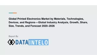
Sintering • Definition: • Sintering is a method for making objects from powder typically below its melting point • Traditionally use Heat, pressure and time • History • 1906 First patent on sintering Using Vacuum by A. G. Bloxam. • Decades of Development with around 640 Patents • Some current methods of sintering: • Sintering Ovens • Arc Discharge • Laser • And now Pulsed Light. Vacuum Sintering Oven Xenon Arc Lamp on a roll to roll system at WMU
Photonic Sintering Basic • Low temperature sintering of metal inks are possible because when particles become small their melting point is reduced. This phenomenon is called “Melting Point Depression” • When particles become small their absorption characteristics change • Nanotechnology is where particles are in the range of 1 to 100nm in size and it is at this particle size that these special effects take place • Nano conductive inks can absorb light and sinter at a low temperature. • Once sintered they behave like bulk material Melting point depression of Gold nanoparticles Quantum Dots are same material but with different size which changes color
Advantages of Photonic Sintering • Conventional method of sintering conductive inks is to use low temperature ovens • The time to achieve sintering is many minutes and not suited to Roll to Roll process • Photonic sintering can take place in fractions of seconds • Photonic sintering is a non contact process • It requires no additional chemicals or special environment • It is a low temperature process allowing use of low temperature flexible substrates like paper and PET • It is easy to configure for different ink types, substrates and printing process. • It can be fitted inline with an existing process without taking the space required for ovens or off-line solutions.
Photonic Sinterable Materials • At Xenon Corp. we have tested many inks from different ink manufacturers here are a few that we can mention. • Copper • Silver • Gold • Nickel • Platinum • ITO
Particle Size of nano-inks Silver (~5 nm) Gold ( 3-4 nm) • Particle Size plays an important role in defining the absorption characteristics of the Nano ink • The tighter the control the better repeatability you have • Using broad spectrum source reduces your dependence on fixed particle size Palladium ( ~3 nm) Platinum ( ~2 nm)
Spectral dependence of Size and shape • Particle shape and size can determine the absorption characteristics of nano-particles. UV-visible extinction spectra of Ag SL PPA
Some Case Studies- Silver • Silver Nano-inks are generally simpler to manufacture and more prevalent • Silver and its oxide are both conductive • They require less energy to sinter • They can show improvement with multiple pulses (reduce stitching effects) • They have a large operational window
Silver Test Results • Chemistry:Nanotech Nanosilver dispersion NT-S05IJ06-46 – 46 % • Substrate: Pebax Green 72 • Dispense Method: Dip • Resistivity: .083 ohms / square • Dose: 657 J / 500 usec pulse • Comment: This application required sintering of a tube, Silver sintered easily, Adhesion was excellent and uniformity good even on a radius.
Case Study - Gold • Chemistry: Nano Gold Dispersion - NTG-05IX-25 • Substrate: Pet • Dispense Method: Dip • Resistance: 5 ohms 1 cm • Dose: 451 J at 500 usec • Comments: This gold is very easy to sinter, The adhesion is excellent and stitching problems minimal BEFORE XENON FLASH AFTER XENON FLASH
Case Study Copper • Chemistry: Applied Nanotech Copper • Substrate: Polyimide • Dispense Method: Drawdown • Resistivity: 13.8 x bulk • Dose: 1 pulse of 304 J – 1000 usec • Application: • This copper requires a fair amount of energy, Adhesion is good, Stitching marks can be seen but the resistivity is good across stitch
Xenon Corp- An Introduction • We manufacture High Energy Pulsed Light systems for industry • We have been established since 1964 • Have developed lamps for laser pumping • Our Markets Include: • Optical disk manufacture • Pulsed UV sterilization • Food enhancement • Surface treatment • Photonic Sintering • We manufacture our own Lamps and Electronic systems • We build “the engine” that integrates into industrial systems that need to run 24/7 • Pulsed light is our expertise we pick up where other sources cannot compete in terms of energy, peak power and low temperature
Xenon at a glance • The leading World Wide provider of High Energy Pulsed Light Technology for industrial applications. • Primary markets: • Printed Electronics • Optical disk: Blu-ray, DVD • Solar • Surface Sanitization • Food Enhancement • 5 patents issued and 4 additional patents pending • Founded 1964 • World headquarters in Wilmington (near Boston), Massachusetts USA
Xenon Corp Sintering Roadmap Copper Sintering MACS 6 6 Lamp Silver Sintering Sinteron 5000 10 Lamp SPEED/ENERGY ROLL TO ROLL Sinteron 5000 5 Lamp START/STOP Active Control Sinteron 2010 Sinteron 2000 Active Control Sinteron 2005 Sinteron 500 2013 2010 2011 2012 Present Day TIME
Products: Sinteron 500 • Used for Sintering Silver inks • Fixed Pulse Width - • Voltage Adjustment
The Sinteron 2000 Our First Copper Sintering Solution for R&D • Developed specifically for the high energies needed for Copper • Pulse width is adjustable • 500 uS • 1000 uS • 1500 uS • 2000 uS • Pulse Voltage Adjustment • 1.5KV to 3.4KV • Lamp can be spiral or linear Lamp Housing • Also has option for Linear Stage for large area processing
The Sinteron 2010 Introduces Active Control • Programmable Pulse width 100-2000us • Voltage Ajustment • 2000 Joules /Pulse • Suitable for Copper Applications
The Sinteron 5000 Our First R2R Offering • Integrated Controller for lamp synchronization • 10 Lamp System • Integrated Conveyor • Integrated Cooling • Touch screen Computer based
MACS-6Our Multi Lamp Active Control System for R2R • Active control • 30 in Lamp • Cassette based Lamp housing for easy removal
Roll to Roll Challenges • Roll to roll applications have unique requirements • Process speeds 5ft/min to 100s ft/min • Faster throughput increases efficiency and reduces costs • Synchronization is important • Web based systems demand higher reliability • Down time and failure generates waste • Web size can vary • Flexibility is required • Different inks, different substrates, different applications • Functional Uniformity of result is important. • Tolerant to ink thickness and printing process
Printing Process • Different kinds of printing processes can be used for Photonic sintering Choice determined by desired thickness and feature size
Printing Technology • The technology is well suited to small scale systems like ink jet printing and small scale gravure printing. • There are many lamp designs that can lend themselves to a retro fit for a staged system • Typically a lot more flexibility in speed, so can be accomplished with a single lamp solution
Process Speed based on Photonic Sintering • For photonic sintering process speeds are defined by the flash rate, energy per pulse and number of flashes required. • For optimal performance the lowest energy required with the shortest pulse needs to be identified for the process. • These define the total energy demand of the system and the required cooling for safe operation of the lamp. • The lower the energy per pulse the faster the lamp can be flashed • Flash lamp systems can be scaled to include multiple sources to keep up with process speed. • Example values for a 16 " lamp housing is 12 " x 1" optical footprint with a pulse rate of 3 Hz = 15 ft /min web speed Optical Footprint Per pulse Flow too fast for Pulse rate Banding Flow Speed Overlap
The Strategy for Successful Deployment • Create R&D low cost tools that can be used for Evaluation of Ink Formulation • Develop Application Lab support for Fast track process development • Create Key Partnerships • ink developers, • print technology groups • substrate manufacturers • process integrators • Academic Institutes • Government Funding • Develop Satellite sites for evaluation of technology • Identify end to end working solutions
Satellite Sites • Xenon corp. understands that successful deployment of photonic sintering requires collaboration with multiple technology groups. • Xenon Corp. has led the formation of a consortium of manufacturers, integrators and universities called Printed Electronics Test Center Network. • This network includes seven US and eleven International sites. These sites offer Laboratory, equipment and expertise to develop printed electronic solutions. Distributors. • Please visit www.xenoncrop.com for more information.
Moving to Roll to Roll- The Future • Large web width sintering • Low energy sinterable inks • Low cost ink/Substrate solutions • High speed printing Capability • Dynamic Monitoring of Functionality • Sinterable semi-conductive materials • Novel interconnect solutions between Flexible electronics and devices
Conclusions • Photonic sintering: • Works with many conductive nanoparticles for printed electronics needs • Requires high energy which can be generated by a flash lamp • fast, compact and cost effective alternative to ovens • easy retrofit to existing process for roll to roll deployment • Needs to be flexible to work with various ink formulations • Should be scalable for different process speeds • Roll to Roll offers unique challenges for pulsed light. • Xenon is developing a strategy which includes all aspects of the development

![[Sintering]](https://cdn2.slideserve.com/3866196/sintering-dt.jpg)