Download
1 / 21
230 likes | 364 Vues
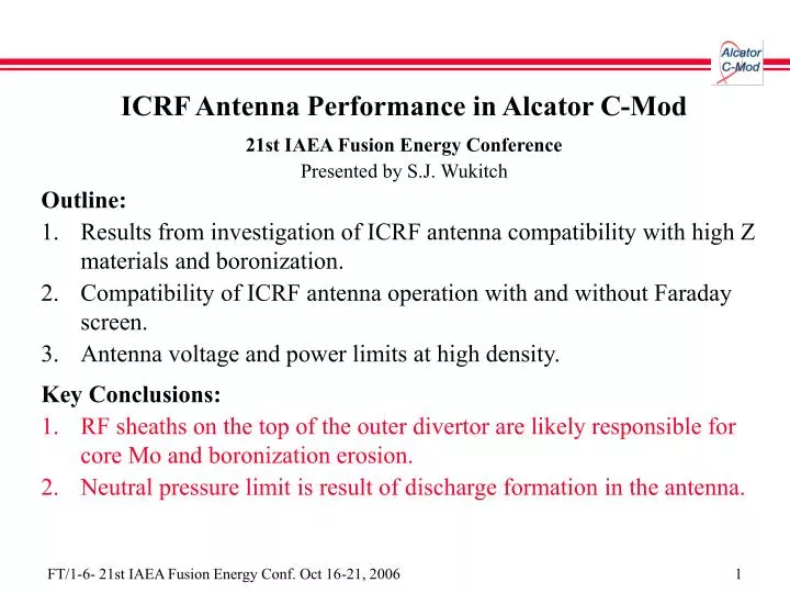
ICRF Antenna Performance in Alcator C-Mod 21st IAEA Fusion Energy Conference Presented by S.J. Wukitch Outline: Results from investigation of ICRF antenna compatibility with high Z materials and boronization. Compatibility of ICRF antenna operation with and without Faraday screen.

E N D
ICRF Antenna Performance in Alcator C-Mod • 21st IAEA Fusion Energy Conference • Presented by S.J. Wukitch • Outline: • Results from investigation of ICRF antenna compatibility with high Z materials and boronization. • Compatibility of ICRF antenna operation with and without Faraday screen. • Antenna voltage and power limits at high density. • Key Conclusions: • RF sheaths on the top of the outer divertor are likely responsible for core Mo and boronization erosion. • Neutral pressure limit is result of discharge formation in the antenna.
Motivation • The antenna is the most critical element to the success of ITER’s 20 MW of ICRF heating power. • Need to reliably couple power to the plasma with minimum negative impact on the plasma. • Predictive capability for antenna performance is currently lacking. • C-Mod shares some important characteristics with ITER ICRF situation. • Plasma facing components are molybdenum (analogous to tungsten in ITER). • Has similar antenna power density and single pass absorption. • To enable ICRF utilization, we seek to develop an understanding • of the RF-plasma edge interactions to minimize impurity production, enhanced sputtering, and localized hot spots; and • the underlying physics that limits antenna power and voltage handling.
ICRF Antenna Basics • The antenna is comprised of a set of current straps. • Couples power to the plasma • but excites some undesirable field components.
ICRF Antenna Basics • The antenna is comprised of a set of current straps. • Couples power to the plasma • but excites some undesirable field components. • Antenna box, RF limiters, and Faraday screen: • Protect antenna from plasma and • Are intended to shield undesirble field components. • But… • increases voltage required to obtain given power and increases RF losses. • Disruption and thermal loads are challenging.
Antenna Performance is Dependent on Plasma Edge • Edge plasma density and density profile determines the antenna coupling efficiency. • Sets the distance to propagation and propagation characteristics. • Coupling is linear and can be accurately modeled. • Transient phenomena also influence antenna voltage and power handling: • ELMs, • Monster sawteeth, • H->L transitions, and • Neutral pressure.
Primary physical mechanism is RF sheaths. Open field lines connect conducting surfaces and enclose RF flux. Electrons are lost preferentially and field lines charge positive. Voltage is dropped across the sheath at limiters, walls, and divertor. Sheaths result in increased impurity and gas production with RF power. Enhanced sputtering from ions are accelerated by the RF sheaths (100-500V). Focus has been on sputtering from Faraday screen and antenna limiters. RF has Strong Impact on Plasma Edge
Achieved High Performance Plasmas with All Metal PFCs • Test high power ICRF compatibility with metallic plasma facing components (as expected on ITER). • Controlling high Z impurities is key to high performance discharges. • Mo is primary core radiator and the fractional Mo concentration <10-4. • Boronization is applied to control high Z impurities. • High Z impurity concentrations are strongly reduced. • World record volume average pressure of 1.8 atm and bN~1.74 (ITER target).
Sheaths on RF Limiters are not Primary Source of Core Mo • Observed clear correlation between RF limiter Mo source rate and core Mo content. • Utilized insulating BN tiles to eliminated sheaths and Mo source local to the antenna. • Plasma performance was unimproved despite lowering the local RF source. B. Lipschultz et al., NF 2001
RF Heated Discharges show Accelerated Erosion • For H-modes with similar input energy, the RF heated discharges show faster erosion rate than ohmic H-mode. • Reduced plasma performance is associated with high plasma radiation. • Erosion rate is ~15-20 nm/s with RF heating. • Corresponds to 20-30 high RF power plasmas for ~200 nm coating and • typically one discharge for thin (~20 nm) coating . • Additional experiments suggest erosion and subsequent Mo source is away divertor strike point. • Localized boronization is optimized plasma performance when applied in the region of the top of the outer divertor. • Post-campaign inspection confirmed B layer did not survive on tiles between 0.65-0.7 m.
Observe Elevated Plasma Potential on Field Lines Connected to Active Antenna • Measured potentials are typically 100-400 V. • Above threshold for D sputtering of Mo. • If RF enhanced sheaths are responsible for accelerated erosion, • The erosion should be localized to the active antenna. • The field lines with the enhanced sheaths should be unaffected by insulating limiters and • Erosion is localized to the top of the outer divertor. • Low plasma radiation can be maintained for consecutive discharges following a light boronization by: • heating the first discharge with Ant 1 and • the second discharge with Ant 2.
Erosion is Linked to Active Antenna • Radiated power significantly increased for second discharge in consecutive discharges heated by single antenna (Ant 1). • Maintained low radiated power for second discharge in consecutive discharges when heated by second antenna (Ant 2).
Open Field Lines Passing Near the Antenna Terminate on Outer Divertor • Open field lines that terminate on top of the outer divertor pass near the antenna will have RF enhanced sheaths. • Antennas have unique toroidal shadow. • Ironically nearly in front of the other antenna.
RF Sheaths are Responsible for Accelerated Erosion • Measured potentials are typically 100-400 V above the threshold for D sputtering of Mo. • Demonstrated erosion is local to active antenna. • The field lines with the enhanced sheaths would be unaffected by insulating limiters and • Field lines terminate on the top of the outer divertor. • Low plasma radiation maintained for consecutive discharges following a light boronization by: • heating the first discharge with Ant 1 and • the second discharge with Ant 2.
Antenna Characteristics are Strong Influence on Erosion/Impurity Generation • J antenna erosion and subsequent impurity generation appears to be slower than D+E antenna. • Suggests details of antenna design impact erosion/impurity generation rate. • Erosion rate unaffected by weak single pass absorption scenario, D(3He).
Test Antenna Operation without a Faraday Screen • Operation antenna without a FS would have several advantages: • remove a potential impurity source, • reduce RF losses, and • simplify the antenna design. • Experimental results for antenna operation without a FS has been mixed. • TEXTOR and Phaedrus-T observed effective heating and plasma performance. • DIII-D had strongly degraded heating effectiveness, voltage and power handling. • ASDEX-U observed 10% reduced heating effectiveness in H-mode. • Replaced Faraday screen on Antenna 2 with Mo septums.
Heating Effectiveness was Significantly Decreased without FS • Heating effectiveness was decreased: • ~10% in L-mode and • 15-20% in H-mode discharges. • Loading, voltage and power handling were unchanged. • Relative Cu density shows strong correlation with antenna without a FS. • Interaction was observed where near the middle of the antenna. • Cu source is from the current straps. • Sheath rectified fields near antenna strap midplane are likely cause of Cu sputtering. • Need to modify antenna strap to minimize sheath fields.
Antenna Voltage Limits at High Density (high neutral pressure) • Observe a neutral pressure limit (~ 1 mtorr) at which voltage and power handling degrade abruptly and unable to recover. • Impacts machine operation at high density. • Phenomenon may be the underlying physical explanation for antenna voltage and power handling degradation with ELM’s. • Despite increased plasma loading and lower antenna voltage, an antenna often faults during ELMs.
Modified Multipactor Discharge is Possible Explanation Time • A multipactor discharge is a resonant condition for electrons in an alternating E field where • Vacuum conditions required and • Electron multiplication from secondary electrons – d(E) > 1. • Find coaxial geometry is more susceptable to multipactor. • For neutral pressure > 1 mTorr, a discharge is formed. • This pressure is ~100x less than minimum in the Paschen curve. • Find magnetic field further reduces the pressure at which discharge forms. e- E1 E2 E3
Modified Multipactor Discharge is Responsible for Voltage Degradation at High Neutral Pressure • Find neutral pressure at which discharge forms is the same as the neutral pressure limit. • Both antenna operational limits agree with onset of modified multipactor discharge. • Tests indicate reducing secondary electron coefficient (d(E)) can raise or eliminate this limit. • Simulations suggests both inner and outer conductor need to have d(E)<1 for coaxial case. • For parallel plate geometry, only one surface needs to have d(E)<1.
Summary • Achieved antenna performance compatible with high performance plasmas with all metal PFCs post boronization. • RF Mo source and erosion location: • RF sheaths are likely responsible for significant core Mo and boronization erosion. • Important location is on the top of the outer divertor (outside the divertor and away from the antenna!). • Important consideration for ITER divertor design. • Screen-less operation: • Present screen-less antenna configuration is incompatible with high performance plasmas. • Reducing RF sheaths by antenna design change is logical next experiment. • Modified multipactor discharge is responsible for voltage degradation at high neutral pressure. Be W C