Download
1 / 37
370 likes | 525 Vues
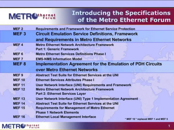
Introducing the Specifications of the Metro Ethernet Forum. Introducing the Specifications of the Metro Ethernet Forum. MEF 2 Requirements and Framework for Ethernet Service Protection MEF 3 Circuit Emulation Service Definitions, Framework and Requirements in Metro Ethernet Networks

E N D
Introducing the Specifications of the Metro Ethernet Forum MEF 2 Requirements and Framework for Ethernet Service Protection MEF 3 Circuit Emulation Service Definitions, Framework and Requirements in Metro Ethernet Networks MEF 4 Metro Ethernet Network Architecture Framework Part 1: Generic Framework MEF 6 Metro Ethernet Services Definitions Phase I MEF 7 EMS-NMS Information Model MEF 8 Implementation Agreement for the Emulation of PDH Circuits over Metro Ethernet Networks MEF 9 Abstract Test Suite for Ethernet Services at the UNI MEF 10 Ethernet Services Attributes Phase I MEF 11 User Network Interface (UNI) Requirements and Framework MEF 12 Metro Ethernet Network Architecture Framework Part 2: Ethernet Services Layer MEF 13 User Network Interface (UNI) Type 1 Implementation Agreement MEF 14 Abstract Test Suite for Ethernet Services at the UNI MEF 15 Requirements for Management of Metro Ethernet Phase 1 Network Elements MEF 16 Ethernet Local Management Interface * MEF 10 * replaced MEF 1 and MEF 5
This Presentation • Purpose • This presentation is intended as an introduction and companion to both the MEF 3 and MEF 8 Specifications • These are the two principal specifications relating to services that carry Circuit Emulation/TM traffic across Carrier Ethernet • Audience • It is intended for Product Marketing, Engineering staff of member companies, for members of other standards bodies, Enterprise networking staff, and service providers who • Would like a quick overview of the specifications • Plan to read the specifications in detail • Other Documents • Presentations of the other specifications and an overview of all specifications is available on the MEF web site • Other materials such as white papers and case studies are also available
MEF Specifications Overview MEF 3 Circuit Emulation Service Definitions, Framework and Requirements in Metro Ethernet Networks Purpose Circuit Emulation Service “tunnels” TDM traffic through a Metro Ethernet network allowing inclusion of legacy networks within a Carrier Ethernet environment Audience Equipment Manufacturers supporting devices that provide Circuit Emulation over Carrier Ethernet Services.Useful for Service Providers architecting their systems. Technical Committee Service Area MEF 8 Implementation Agreement for the Emulation of PDH Circuits over Metro Ethernet Networks Purpose Gives precise instructions for implementing interoperable CES equipment that reliably transport TDM circuits across Metro Ethernet Networks while meeting the required performance of circuit emulated TDM services as defined in ITU-T and ANSI TDM standards Audience Equipment Manufacturers supporting devices that provide Circuit Emulation over Carrier Ethernet Services.Useful for Service Providers architecting their systems. Technical Committee Service Area
MEF 3: CES Framework & RequirementMEF 8: CES Implementation Agreement • Industry’s first formal definition of CES standards over Ethernet • A services description • Types of TDM services offered over Metro Ethernet, • PDH and SONET/SDH • DS1E1, DS3/E3, OC-3/STM-1, OC-12/STM-4 • A requirement document • Comprehensive CES requirements for providing TDM services over Ethernet • SLA service quality parameters as specified by the ITU for TDM services • An implementation agreement for Ethernet • Practical agreement as to how to implement the CES over Ethernet
What is Circuit Emulation Service over Carrier Ethernet? • Circuit Emulation Service “tunnels” TDM traffic through a Metro Ethernet network • packet network “emulates” a circuit-switched network, re-creating the TDM circuit at the far end • invisible to TDM source and destination equipment • runs on a standard Ethernet Line Service (E-Line) Metro Ethernet Network TDM Circuits (e.g. T1/E1 Lines) TDM Circuits (e.g. T1/E1 Lines) TDM Pipe
MEF 3 TDM Circuit Emulation • Support Traditional PDH/SONET/SDH hand-offs to existing customer voice equipment • Allow Interworking onto Ethernet EVCS across the MEN. Types: 1)Unstructured - all bits in must be sent across to the destination 2) Structured - Requires only sending TDM payloads not the over head
Circuit Emulation Services Relationship to the Metro Ethernet Network • CES functions in relation to those specified by the MEF for the MEN
Functions Defined • TSP - Optional TDM mux/demux function –prior to Ethernet interworking • IWF - Interworking function of TDM to Ethernet frames • ECDX - Identifier function for proper forwarding and demultiplexing • EFTF –Addressing and FCS functions.
Functions applied • ECDX as shown is effectively a multiplexing function allowing multiple CES circuits to share a single EVC MEN
Functional Layering, and mapping onto encapsulation headers • Treats the MEN as a “virtual wire” between two TDM networks
MEF Service Definitions • TDM Line Service (T-Line): • Application: Leased line replacement Customer Premises Customer Premises CESoETH CES IWF CES IWF TDM Ethernet Ethernet TDM Metro Ethernet Network E-Line Service Ethernet UNI Ethernet UNI Service Provider Network TDM subscriber demarcation TDM subscriber demarcation
MEF Service Definitions PSTN • TDM Access Line Service (TALS): • Application: Access to a remote network (e.g. PSTN) Customer Premises CESoETH CES IWF CES IWF TDM Ethernet Ethernet TDM Metro Ethernet Network E-Line Service Ethernet UNI Ethernet UNI Service Provider Network TDM subscriber demarcation TDM Network Interface
MEF Service Definitions • Customer-Operated CES: • Application: Toll-bypass Customer Premises Customer Premises CESoETH CES IWF CES IWF TDM Ethernet Ethernet TDM Metro Ethernet Network E-Line Service Ethernet UNI and subscriber demarcation Ethernet UNI and subscriber demarcation Service Provider Network
MEN CoS Performance Parameters To ensure proper CES IWF operation service quality: • Ethernet Frame Delay should be minimized • to meet MEF 5 defined parameters • Ethernet Frame Delay Variation • MEN EVCS jitter up to 10 ms max • Ethernet Frame Loss • ESR and SESR should meet TDM requirements • Network availability • should meet 99.95% TDM requirement
PDH Interoperability Agreement –MEF 8 Specifies Interoperability requirements for: • Connectivity • Timing • Signaling • MEN performance criteria • MEN services OAM
Emulated Circuit Identifier ECID • – identifies the emulated circuit being carried. • Separates the identification of the emulated circuit from the Ethernet layer, • allowing the MEN operator to multiplex several emulated circuits across a single EVC where required. • This is added by the ECDX.
CESoETH control word • Provides sequencing and signaling of defects • such as AIS of the TDM circuit, or packet loss detected in the MEN. • This is added by the CES IWF.
Standards for Synchronization PSTN PSN E1 standards (2.048 Mbps) • Traffic interface (G.823, Table 2) • 18 s over 1000s T1 standards (1.544 Mbps) • Traffic interface(T1.403, section 6.3.1.2) • 8.4 s over 900s • 18 s over 24 hours Central Office Remote Terminal Customer Premises PRS CESoP IWF TDM Equipment CESoP IWF T1/E1 T1/E1 CES induced wander < 18 ms Max. end-to-end wander (traffic interface) 18 ms
Timing • Synchronous services require timing be provided • Line, through, external or internal timing mode options • Applies to structure aware only • Synchronization. • the clock used to play out the data at the TDM-bound IWF must be the same frequency as the clock used to input the data at the MEN-bound IWF, • otherwise frame slips will occur over time
Timing options • TDM line timing • use the clock from the incoming TDM line • External timing • use an external reference clock source • Free run timing • use a free-running oscillator • Ethernet line timing • recovering the clock from the Ethernet interface
Signaling • Structure Aware CESoETH must provide signaling • CE Common Channel Signaling (CCS) • Can be carried within the emulated service data • CE Common Channel Signaling (CAS) • Must be handled separately for Nx64 service- Encoding Format for CAS • Note must have a separate Control Word from the Data, but can share same ECID
Performance Monitoring • Facility Data Link • May monitor but not change DS1 Extended Super Frame message data • Errored Data • CESoETH should be capable of monitoring Frame Error ratio
MEN Service & SLA Requirements • MEN service quality assurance is critical to maintain consistent quality of the carried TDM service • SLA service quality parameters should support to those specified by the ITU for TDM services • Nx64 Services require CAS Signaling in MEN • SDH/SONET requires pointer adjustments in MEN • Specified MEN Quality Parameters: • Frame Delay: <25ms • Jitter (Delay Variation): <10ms • Frame Loss/Errors Ratio (FER) For SONET/SDH: • Errored Seconds (ES) • Severely Errored Sec (SES) • Background block SES (BFER)
Frame Delay Defined • The time required to transmit a service frame from source to destination across the MEN. Measured from 1st bit in to last bit out
Frame Delay Variation Defined • The difference in delay of two service frames. CE CE CE CE Metro Ethernet Metro Ethernet Network Network Frame 1 time first bit in first bit in UNI to UNI UNI to UNI Frame Delay Variation1 Frame Delay Frame 2 first bit in Frame 1 last bit out Frame Delay Variation 2 Frame 2 Last bit out
Frame Loss Defined • Frame loss is a measure of the number of lost service frames inside the MEN. • Frame loss ratio is % = # frames lost / # frames sent CE CE CE CE time Metro Ethernet Metro Ethernet Network Network 5000 frames in UNI to UNI UNI to UNI 4995 frames out 5 frames lost/or received as errored 0.1% Frame Loss Ratio (5/5000)
MEN Frame Loss Errors –PDH Limits • PDH ES • PDH SES
Other MEN Parameters • Emulated Circuit Availability 99.95% • Emulated Circuit Restoral < 50 ms • Suggested MEN Bandwidth increments • 100 kbps
MEF Services OAM • Alarms • Misconnection alarm (section 6.6.1) • Loss of Frames alarm (section 6.6.2) • Late Frames alarm (section 6.6.3) • Malformed Frames alarm (section 6.6.4) • Jitter buffer overrun alarm (section 6.6.5)
Management – Alarms • Misconnection Alarms – MEN defects: • Stray Frames Must be discarded • CES IWF must check the Ethernet Source address field • Should report an alarm • if stray frames persists above set threshold (Default 2.5 seconds) • Alarm should be cleared • if no stray frames received for a configurable period of time (Default 10 seconds) • Mechanism for detection of lost frames Must Not be affected by reception of stray frames
Management – Alarm Statistics Counters • MEN bound • Frames transmitted • Payload octets transmitted • TDM bound • Frames received • Payload octets received • Lost frames detected • Out-of Sequence frames • Transitions to the LOFS (Loss of frame state) • Malformed frames received • Jitter buffer overruns • Jitter buffer underruns
Similar work in other bodies • ITU-T: Recommendation Y.1413 • Very similar to MEF8, but for MPLS networks rather than Metro Ethernet • Payload and encapsulation formats are identical • Equipment supporting Y.1413 should also be capable of supporting MEF8
Similar work in other bodies • IETF: draft-ietf-pwe3-satop-01.txt, draft-ietf-pwe3-cesopsn-02.txt, draft-ietf-pwe3-tdmoip-03.txt • Very similar to MEF8, but for IP and MPLS networks rather than Metro Ethernet • As with Y.1413, payload and encapsulation formats are identical • Equipment supporting Y.1413 should also be capable of supporting these IETF drafts
For Full Details … Subscriber Site Subscriber Site Subscriber Site Subscriber Site Video Source … visit www.metroethernetforum.org to access the full specification Metro Carrier Ethernet Internet Global/National Carrier Ethernet Access Carrier Ethernet Hosts, Legacy Services, Remote Subscribers etc Service Provider 1 Metro Ethernet Network Service Provider 2 Metro Ethernet Network