Download
1 / 42
430 likes | 572 Vues
Introducing the Specifications of the MEF. MEF 31: Service OAM Fault Management Definition of Managed Objects July 2012. Outline. Approved MEF Specifications This presentation About this Specification In Scope / Out of Scope Terminology, Concepts & Relationship to other standards

E N D
Introducing the Specifications of the MEF MEF 31: Service OAM Fault Management Definition of Managed Objects July 2012
Outline • Approved MEF Specifications • This presentation • About this Specification • In Scope / Out of Scope • Terminology, Concepts & Relationship to other standards • Section Review • Major topics • Minor topics • Examples/Use Cases • Summary
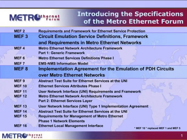
Approved MEF Specifications* *Current at time of publication. See MEF web site for official current list, minor updates and superseded work (such as MEF 1 and MEF 5)
Approved MEF Specifications *Current at time of publication. See MEF web site for official current list, minor updates (such as MEF 31.0.1 amendment to this document) and superseded work (such as MEF 1 and MEF 5)
MEF Specification Overview MEF 31 - Service OAM (SOAM) Fault Management Definition of Managed Objects Purpose Specifies the Fault Management (FM) Management Information Base (MIB) necessary to implement Service Operations, Administration, and Maintenance (OAM) that satisfies the Service OAM requirements and framework specified by MEF 17, MEF 30, the management objects specified in MEF 7.1, and the FM functions defined in IEEE 802.1ag and ITU-T Y.1731. Audience Applicable to entire Metro Ethernet Market including Service Providers, Access Providers, equipment vendors, and EMS/NMS/OSS vendors to provision and monitor equipment that is MEF compatible. Standardized Services
About MEF 31 • Purpose: • This presentation is an introduction to MEF 31 - Service OAM Fault Management Definition of Managed Objects • Audience • Equipment Manufacturers building devices that will carry Carrier Ethernet Services • Service Providers delivering Carrier Ethernet Services • EMS/NMS/OSS tool vendors developing back office applications for managing Carrier Ethernet Services • Other Documents • Presentations of other MEF specifications and an overview of all specifications is available on the MEF web site • Other materials such as white papers and case studies are also available
MEF 31 - In Scope/Out of Scope • MEF 31 requirements are primarily driven by MEF 30 and leverage the OAM functions & managed objects defined by IEEE 802.1ag/ap and ITU-T Y.1731 • Managed objects to perform Fault Management functions such as Continuity Check, Loopback and Link Trace are covered in this Technical Specification • SOAM Performance Management capabilities will be covered in future a MEF document
Terminology and Concepts • MEF 31 adheres to MEF 30 terminology: • Refer to MEF 30 for ME, MEG, MEP, MIP, CoS • Continuity Check Message (CCM) • Alarm Indication Signal (AIS) • Remote Defect Indication (RDI) • MEF 31 introduces protocol specific terminology • Simple Network Management Protocol (SNMP) • SNMP Manager • Management Information Model (MIB) • Element Management System (EMS) • Network Management System (NMS) • Operations Support System (OSS) MEF-30 aligns with terminology found in ITU Y.1731
MEF Service Lifecycle and SOAM Network Management Fault management is a critical part of a circuit’s lifecycle
Introducing MEF 31 • The presentation is broken into sections: • Overview • Network Management Concepts/Topologies • Initial Configuration • OAM Functions • Configuration • Status • Summary • Where to find additional information
What is a MIB? A Management Information Base (MIB), or data model, is a collection of managed objects that can be used to provision or query a network device from a management system, such as a centrally located NMS (Network Management System). A MIB along with the management protocol, such as SNMPv2c, defines a standard network management interface for administration and maintenance of network elements. Configuration and Monitoring Data MIB Network Element Network Management System
Management Framework UNI UNI Trouble Ticket System Notify SNMP SNMP MIB MIB MIB ENNI MIB MIB MIB Operator 1 Network Operator 2Network NID NID CPE CPE O Network Management System Ethernet Virtual Connection SP Network Ops Service OAM ITU-T Y.1731End-to-End Performance Monitoring IEEE 802.1agEnd-to-EndConnectivity Fault Management
SOAM FM MIB Components • MEF 31 builds upon the Connectivity Fault Management (CFM) MIBs specified in IEEE 802.1ag and IEEE 802.1ap • The IEEE CFM MIB set includes • IEEE8021-CFM-MIB • IEEE8021-CFM-V2-MIB • IEEE8021-TC-MIB • MEF 31 extends the CFM MIB set as follows • MEF-SOAM-TC-MIB • MEF-SOAM-FM-MIB
SOAM TC MIB Overview • MEF-SOAM-TC-MIB defines a collection of Textual Conventions (common data types) • ConnectivityStatusType • DataPatternType • IntervalTypeAisLck • MegIdType • OperationTimeType • TestPatternType
SOAM FM MIB Overview • MEF-SOAM-FM-MIB defines the managed objects necessary to support SOAM FM functionality: • Continuity Check (CCM) • Remote Defect Indication Signal (RDI) • Alarm Indication Signal (AIS) • Linktrace • Loopback • Locked Signal • Test Signal
Initial SOAM Configuration via 802.1ag/ap MIBs • Before SOAM operations are instantiated by a NMS application, the following must be provisioned at each Network Element (NE) performing OAM Functions: • Maintenance Domain (MD) • Create entry in dot1agCfmMdTable • Maintenance Association (MA)/Maintenance Entity Group (MEG) • Create entry in dot1agCfmMaNetTable, ieee8021CfmMaCompTable, mefSoamNetCfgTable and mefSoamMegCfgTable • MEG End Point (MEP) • Create entry in dot1agCfmMepTable
Continuity Check Configuration Entries • These 2 tables configure the Continuity Check OAM function with the associated parameters
Continuity Check Status/Result Entries • These 2 tables provide the status and results of the Continuity Check OAM function **Not directly related to the CCM OAM function but included here for Table completeness
Loopback Configuration Entries • These 2 tables configure & invoke the Loopback OAM function with the associated parameters
Loopback Status/Results Entries • These tables provide the status and results of the loopback OAM function
Alarm Indication Signal Configuration Entries • This table configures & invokes the Alarm Indication Signal (AIS) OAM function with the associated parameters
AIS Status/Results Entries • This table provides the status and results of the Alarm Indication Status OAM function
Linktrace Configuration Entries • This table configures & invokes the Linktrace OAM function with the associated parameters
Linktrace Status/Results Entries • These tables provide the status and results of the loopback OAM function Continued
Linktrace Status/Results Entries (cont) Continued
Locked Signal Configuration Entries • This table configures & invokes the Locked Signal OAM function with the associated parameters
Locked Status/Results Entries • This table provides the status and results of the Locked Signal OAM function
Remote Defect Indication Signal Configuration Entries • This 2 table configures the Remote Defect Indication (RDI) Signal OAM function with the associated parameters **RDI is a 1-bit information element carried in the Flags field of the CCM OAM PDU and is enabled through the CCM function.
RDI Status/Results Entries • These tables provide the status and results of the Remote Defect Indication OAM function
Test Signal Configuration Entries • This table configures & invokes the Test Signal OAM function with the associated parameters
Test Status/Results Entries • This table provides the status and results of the Test Signal OAM function
Alarm Configuration • These following objects provide alarm configuration for the 802.1ag CFM and MEF SNMP Notifications
SNMP Notifications • These following MEF SNMP Notifications provide for Autonomous alarms and events
Summary MEF 31 MEF 31 defines the managed objects for using an SNMP management interface for the MEF 30 Service OAM Fault Management protocol MEF 31 enables MEF equipment providers to provide a standardized management interface for the SOAM Fault Management functions: Continuity Check/Remote Defect Indication Loopback Linktrace Alarm Indication Signal Lock Signal Test Signal
Final Word • Service OAM • In the context of MEF 31, data models (MIBs) are defined that support service-level OAM in MENs • Next Actions (For Further Information) • Read the full MEF 30 Fault Management Implementation Agreement specification • Read the full MEF 31 specification (note, review of MEF 17, MEF 7.1 and MEF 15 may also be helpful) • Understand the principal service OAM components and capabilities
For Full Details … Please visit www.metroethernetforum.orgSelect Information Center on Left Navigation to access the full specification and extracted MIB files E-Line Service type Carrier Ethernet 2.0 EVPL Services UNI E-LAN Service type Carrier Ethernet 2.0 EVP-LAN Service UNI Internet ISP POP UNI CE EVC: Ethernet Virtual Connection UNI: User Network Interface. the physical demarcation point between the responsibility of the Service Provider and the responsibility of the End-User/Subscriber CE Customer Equipment CE UNI CE Carrier Ethernet Network CE Carrier Ethernet Network CE UNI CE UNI
Accelerating Worldwide Adoption of Carrier-class Ethernet Networks and Services www.MetroEthernetForum.org