Download

1 / 22
220 likes | 389 Vues
EC front unit status. S. Ahmad, P. Barrillon , S.Blin , D. Cuisy , S. Dagoret-Campagne , P. Dinaucourt , R. Sliwa , JL. Socha (LAL) A. Ebersoldt (KIT) 8 th progress meeting EUSO-Balloon October 12 th 2012 - APC. Outline. Conclusions from mechanical prototype and actions taken

E N D
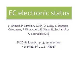
EC front unit status S. Ahmad, P. Barrillon, S.Blin, D. Cuisy, S. Dagoret-Campagne, P. Dinaucourt, R. Sliwa, JL. Socha (LAL) A. Ebersoldt (KIT) 8th progress meeting EUSO-Balloon October 12th 2012 - APC
Outline Conclusions from mechanical prototype and actions taken Status of electrical prototype KIT’s work for TA Dev plan (tests)
Reminder: EC-front elements UV filter MAPMT MAPMT MAPMT • Per EC unit: • 1 EC-DYNODE board • 4 EC-ANODE boards • 1 EC-HV boards Flexible pcb toward EC-back HV cables toward HV box • 3 different PCBs: • First one (EC DYNODE board) allows to reroute half of the dynodes of 1 MAPMT so that they are aligned perpendicularly to the others. It covers the 4 MAPMTs. • Second one (EC ANODE board) covers one MAPMT but has dimensions reduced allowing a flex pcb to get out. It is used to collect signal from the anodes and send them to the ASICs. • Third one (EC HV board) covers one MAPMT. It welcomes the dynodes and supplies the HV to the EC-dynode board which transmits it to the 4 MAPMTs.
6 mm outer diameter 3.1 mm inner diameter Dimensions of PDM frame Radius of the corner : R2.2 17 mm 19.62 mm 19.62 mm 11 mm 6 mm Outer and inner diameters 10 and 6 mm Thickness: 1 mm 55 mm ~2 mm 53 mm 17 mm Thickness: 3 mm 51 mm 9.3 mm Front view
EC unit inside PDM frame Ec_dynode Ec_anode Ec_HV MAPMT MAPMT EC_dynode is 54.5 mm x 54.5mm therefore it will lay on the PDM structure where the distance goes from 55 mm to 53 mm 2 adjacent EC_anodes soldered to the MAPMT pins (going through holes of the EC_dynode) should fit in 53 x 53 mm The EC_HV soldered to extensions coming from the EC_dynode should fit also in the 53 x 53 mm
EC unit assembly test at APC It looked ok…
MATRA mechanical prototype Mechanical prototype The mechanical prototype was finished 12/07 MATRA people checked if the proto was fitting inside a homemade version of the mechanical structure of 1 EC unit They observed that the EC_anodes and EC_HV were overlapping with the structure meaning that they were going over the 53 x 53 mm… Calculations based on the CAD files showed that indeed the dimensions of EC_anode and EC_HV are lightly too much… see following slides.
EC_dynode dimensions 8.32 mm
EC_anode dimensions 6 mm (8.32 – 2 x 1.16) 23.7 mm 24 mm 1.16 mm 53.7 mm 1.16 mm The distance (6 mm) between two EC_anodes is needed to let the flexible cables go through this gap. It was the leading idea of the EC front unit design. But then the global dimensions are 53.7 x 53.7 mm… we missed that .
How to fix the problem for the EC_anodes The larger holes on the edge are 2 mm large ones and there is no routing around. Therefore EC_anode rigid pcb could be reduced significantly by removing the parts MATRA did that on the mechanical prototype to perform the potting test. 1.16 mm 1.16 mm
New version of the EC_anodes and EC_HV Action: EC_anodes were corrected end of July 2012. EC_HV in September 2012. In this version, the extension pins coming from the EC_dynode toward the EC_HV will go next to the EC_anodes not anymore through. 6 mm 21.7 mm 21.1 mm 48.8 mm
New version of the EC_anodes and EC_HV Action: EC_anodes were corrected end of October/beginning of November Now Before 6 mm 21.7 mm 21.1 mm 48.8 mm
Mechanical prototype potting Top view (fake filters) Bottom view (cables and screw) Lateral view 1 Lateral view 2 Lateral view 3 Lateral view 4
Mechanical prototype potting • Clearly the result is not good. • MATRA thinks that the problem comes from the fact that the EC_dynode lays on the mold’s shoulder (from 55 mm to 53 mm), this way the air can not easily escape and this creates bubbles that explode. Mold 3D view from MATRA EC_HV EC_anodes Ec_dynode • Actions: • Modification of the mold (sept 2012) • Potting will be done in vacuum MAPMT MAPMT Picture of the mold (2 parts) Filters
Integration of the mechanical prototype potted After all (reduction of the size of the fake pcbs and removal of the central column), it fits in the mechanical frame
Electrical prototype • Due to manpower issue, MATRA started the electrical prototype of the EC beginning of this week • It should be ready next week • It is be composed of: • 4 real MAPMTs equipped with UV filters selected by Philippe • 1 EC_dynode real PCB • 2 EC_anodes of each type real PCB (old version) • 1 EC_HV (old version) • All pcbs have been provided by KIT from the spares of boards produced for TA. • KIT is in charge of the assembly of the EC front units for TA and has started assembly tests
TA EC front unit Slidesfrom Andreas E.
TA EC front unit Slidesfrom Andreas E.
Development plan (tests) • Once the EC front unit electrical prototype will be produced • Connection to the HVPS and HV ON to check current and MAPMTs power and analog signals, without light (in black box) • Connection to the HVPS and HV ON to check current and MAPMTs power and analog signals, with light ON (in black box) • When we will have a working EC_ASIC – test_EC_ASIC couple • EC_ASIC tests with EC front unit without potting (2 weeks) • HV off (Pedestal measurements, DAC linearity, PC measurements) • HV on (same measurements as above) in black boxe, light off • HV on (same measurements as above) in black boxe, light on • EC_ASIC tests with EC front unit with potting (as much time as needed) • HV off (same measurements as above) • HV on (same measurements as above) in black boxe, light off • HV on (same measurements as above) in black boxe, light on • EC_ASIC tests with EC unit at 3 mbar + temperature tests • To be specified
Mechanical prototype: fakeMAPMTs 4 pieces produced by MATRA for the mechanical prototype With fake UV filter as well
Fake pcbs of the EC-front boards EC_HV EC_dynode EC_anodecurved EC_anode straight