Download
1 / 37
370 likes | 496 Vues
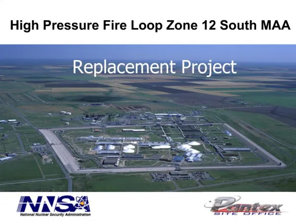
High Pressure Fire Loop Zone 12 South MAA. Replacement Project. HPFL System Overview. The HPFL consists of: Looped and gridded distribution mains ranging from 8 to 18 inches in diameter ~75,000 feet of main line piping Two ground storage reservoirs (360,000 gallons each)

E N D
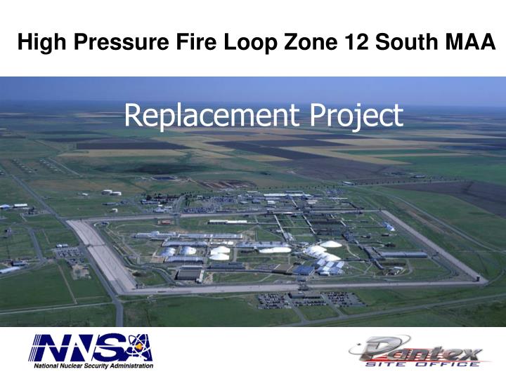
High Pressure Fire Loop Zone 12 South MAA Replacement Project
HPFL System Overview The HPFL consists of: • Looped and gridded distribution mains ranging from 8 to 18 inches in diameter • ~75,000 feet of main line piping • Two ground storage reservoirs (360,000 gallons each) • Two fire pump stations (electric and diesel fire pumps in each)
HPFL Project Overview • Overview • Replace ~ 14,000 feet of Ductile Iron pipe with High Density Polyethylene (HDPE) • Replace Sectional and Lead-in post indicating valves • Install new Sectional valves • Replace Hydrants and isolation valves • Install new valve supervision on Post Indicators • Install new passive cathodic protection on all metallic parts
HPFL Project Management • The ~14,000 feet for piping is sequenced into 10 alignment phases. • The alignments allowed for smaller manageable sections. • The alignments helped with the following; • Reduced the fire protection system down-time. • Reduce scope for start-up tests, QA reviews, and document turnover. • A kick-off meeting was performed prior to starting each alignment. • The kick-off meetings were high level meetings that informed senior management, operations, and security about the scope of each construction phase. This included facility impacts, areas of construction, and cut-over sequencing. • Weekly project meetings are held with PXSO, B&W and the sub-contractor. • Outages for mainline and building tie-ins planned for weekends to limit impact on operations .
Quality Assurance / Quality Control • Field Contractor submitted QA Plan meeting NQA-1 requirements for B&W QA to approve. • Field Contractor to perform and document receipt inspection of all materials & equipment • Materials to be procured from NQA-1 vendors or approved for use via Commercial Grade Dedication process • B&W to approve all Commercial Grade Dedications • Field Contractor to incorporate previously identified and agreed upon hold points into work schedule • B&W to perform inspections at hold points • Field Contractor not to proceed until Hold Point has been inspected, accepted and released by B&W Construction Management or designated SME • QA / QC inspections and documentation reviews to be performed in parallel with construction activities • Required to support placement of system into service immediately following completion of building tie-ins • Project Turnover and Acceptance to be complete at time of lead-in cutovers
HDPE Pipe Welding Secure Each component that is to be fused must be held in position so that it will not move unless it is moved by the clamping device. Face The pipe ends must be faced to establish clean, parallel mating surfaces. Most, if not all, equipment manufacturers have incorporated the rotating planer block design in their facers to accomplish this goal. Facing is continued until a minimal distance exists between the fixed and movable jaws of the machine and the facer is locked firmly and squarely between the jaws. This operation provides for a perfectly square face, perpendicular to the pipe centerline on each pipe end and with no detectable gap.
HDPE Pipe Welding Align The pipe profiles must be rounded and aligned with each other to minimize mismatch (high-low) of the pipe walls. Melt Heat the ends of the pipe to the pipe manufacturer’s recommended temperature, interface pressure, and time duration. By doing so, the heat will penetrate into the pipe ends and a molten “bead” of material will form at the pipe ends. Heating tools which simultaneously heat both pipe ends are used to accomplish this operation. Join After the pipe ends have been heated for the proper time and to the proper temperature, the heater tool is removed and the molten pipe ends are brought together with sufficient pressure to properly mix the pipe materials and form a homogeneous joint. The pipe manufacturer’s instructions may specify either interface pressure or bead size of molten material as a guide for a proper joint.
HDPE Pipe Welding Hold The molten joint must be held immobile under pressure until cooled adequately to develop strength. The designs of the machines vary from a lever-arm-assist to manual or automatic locking devices that assist the operator to accomplish this step. The proper cooling times for the joint are material-, pipe-diameter-, and wall-thickness dependent and are established by the pipe manufacturer. Allowing proper times under pressure for cooling prior to removal from the clamps of the machine is important in achieving joint integrity.
Testing and Acceptance Details • All HDPE fusion welding to be inspected and accepted • A “sacrificial” test weld is completed at the start of each shift and after 20 welds. • The HDPE piping and weld is cut length wise to inspected for acceptable fusion and “bend” testing. • The test piece is cut ~3’ on each side of the weld. This piece is bent until both ends touch. This exerts stress on the weld to ensure they will not fail during use. This test was performed using a jig and hydraulic jack. During the project only one bend test has failed. This weld was from a 14” DR9 pipe. An NCR was performed on the failed weld. It was determined to be a cold fuse due to wind blowing in the open pipe ends. All welds performed that day were considered suspect and cut out. • All flanged connection bolt torque values are documented. • A torque log is kept for all bolts subject to pressure. • All alignments were hydrostatic tested and flushed.
Main Line Flushing • Flushing is performed to help ensure any debris is removed from the new section of pipe. • Flushing is conducted prior to connected to the main line to the buildings. • The first alignment was flushed using a fire pumper truck to ensure cleanliness before connecting to the existing piping. • The additional alignments were conducted by flushing in the direction of construction. • To ensure cleanliness 10 fps water velocity was used. In some section based on pipe diameter this could not be achieved until additional section where placed into service. • Each hydrant and every valve was fully operated under the 10 fps water flow to ensure proper operation. • Residual water pressure was obtained from upstream hydrants to verify proper water flow.
Hydrostatic Testing • Hydrostatic testing is performed to ensure structural integrity of the pipes, fittings, and joints. • Hydrostatic Testing of HDPE piping required several phases due to the pipe expansion. • Piping sections had to be fitted with air vents ensure air has be exhausted from the system. • The piping is then pressurized to 225 psi and allowed to stand for one hour. • After the 1st hour the piping is filled with make-up water and restored to 225 psi. • After the 2nd hour the piping is filled with make-up water and restored to 225 psi. • After the 3rd hour the piping is filled with make-up water and restored to 225 psi. • The piping section is now held for two more hours, after this time make-up water is added to the piping and recorded. Ensure the make-up water is less than ____ gallons. The gallons is a function of pipe size and length. Water is pulled from a graduated container.
Horizontal Directional Drilling (HDD) Process Planning Every bore began with thoughtful planning. Ground conditions are determined, surrounding utilities positively located, bore profile is surveyed and plotted, safety and environmental issues are considered before work started. An entrance and exit pit are dug. Pilot Hole The process begins with the Direction Drill machine pushing a bore head connected to hollow pipe into the ground at an angle. As each joint of drill pipe is pushed into the ground, a new one is added behind it. This process is continued until the bore head comes out of the ground at the exit pit.
HDD Process Guiding and Steering the Bore Head A “Walk Over” Locating system, such as a Sonde (Transmitter), is used with the bore head, to register angle, rotation, magnetic direction and temperature data. The information is then encoded into an electro-magnetic signal, which is transmitted through the ground to the surface. At the surface, a receiver is manually positioned over the Sonde signal, the signal is decoded and steering directions are relayed to the operator of the drill machine. Drilling Fluid From the drill head flows a high-pressure jet of drilling (boring) fluid, which is generally a mixture of bentonite clay and water. Boring is accomplished through the cutting action of the jet of fluid and/or a rotating drill bit. The drill fluid cuts soil, suspends and carries cuttings out of the bore hole, seals the bore hole, lubricates and cools the pipe.
HDD Process Reaming Upon reaching the exit pit, the bit is detached and the end of the drill pipe is attached to a reamer. The reamer is pulled back while rotating the drill pipe with as many passes as required to open up the correct diameter of hole to allow the pipe to be installed. Pull Back Once the bore hole is the correct size for the pipe to be installed, it is attached to the end of the reamer and pulled through the hole. Throughout this process, bore fluid is being continually pumped into the hole to ensure that the hole is sealed with no void being left between the pipe and the native soil.
HDD Advantages • HDD was used to pull long runs of fused piping. • Advantages • Able to go under obstructions • No damage to roadways, ramps, or vegetation • Eliminates backfill and compaction, except in the valve locations • Helps reduce cutting unknown services • No open trench that might impede security or fire services. • Eliminates large dirt piles, which are a security concern • Each pull included the water supply piping and two 2” HDPE pipes to run tracer wire and valve supervision wires. • Enabled the project to get back on schedule.
Cathodic Protection • Cathodic Protection was used on all ferrous fittings and valves. • All metal components were cad welded together and connected to passive cathodic anodes. Test stations were installed with every anode. • Also all metals components were coated with wax and wrapped in plastic film to keep out dirt and moisture. • Rock shield mating was used between concrete pads and valve bodies.
Safety System Oversight Activities • Safety System Oversight (SSO) was performed at various stages throughout the project. • Weekly field walkdowns were performed with the Project Engineer/Facility Representative and observed the following: • Material staging • Workmanship • Drawing walk downs • Safety (e.g. shoring) • Pipe Fusing • Lockout/Tagout • Hot work permits • M&TE • Reviewed and observed acceptance tests • Attended Weekly progress meeting with the Field Contractor and the M&O.
Safety System Oversight Activities • Worked with the Facility Representative, Quality Assurance, and Project Manager to develop an Acceptance Checklist for each Alignment • Each checklist verified the following: • Surveillance Requirements were met • Weld tests • Red-line drawings met field conditions • Fire Department Pre-Fire Plans revised • Test procedures revised • Participated in field walk downs and developed A & B punch list items • A quality assessment is being scheduled for the 4th quarter of FY11.
Lessons Learned • Unmarked electrical duct banks required the piping to be installed 12 feet below grade, 6 feet more than design. • The connection between the ductile iron to HDPE piping had severe corrosion requiring an additional 10 feet of HDPE piping and excavation. • All connections were inspection by the Cathodic Protection System Engineer prior to tie-in. • The incorrect gaskets on the Mueller Hydrants with Aquagrip system were ordered and received. • Unless specified, Mueller sends Ductile Iron pipe size (DIPS) gaskets. • The Iron Pipe Size (IPS) gaskets work with HDPE and are orange in color. • It was not identified until it failed the hydrostatic test. • Specification identified non purcureable items • FM Approved Class 200 DR9 pipe and fittings do not come in large sizes. • FM approved DR7 fitting for class 200 had to be used. • A transition fitting from HDPE to existing Ductile Iron piping was discovered leaking several days after the in-service leak test. Thought to be caused by not properly tamping the dirt under the pipe.
Lessons Learned • The PIV’s that were procured did not meet the design specifications • The PIV’s are designed to break off at the ground level during an explosion. They were captured on the NQA-1 inspection. • Redesign of alignments for constructability due to underground obstructions. • Developed a new process for field changes to ensure they are reviewed and approved by the project and system engineer. • Field condition was discovered not to match controlled drawings. • Resulted in an energized section of piping that was cut. • Additional controls were put in place to ensure personnel and nuclear safety.
Lessons Learned • Trench excavating during the first alignment delayed the project due to known and unknown obstructions. • Electrical duct banks were deeper and wider than shown on drawings. • Could not achieve 10 fps of water flow on some sections of piping through hydrants. • Test connections were fabricated out of large HDPE piping. • Ensured flows greater then the largest flow facility was achieved. • Pitting as much as 90% of the wall thickness was discovered on the facility lead-in piping • Snap Wrap was a product added to the project specification for existing ductile iron piping • Failure to use foreign material exclusion caps on the end of piping could have led to obstructions in the sprinkler piping. • The make-up water for the hydrostatic test was not being accurately measured. • Ensure that the contractor is aware of all the material specified in the design. • HDPE anchor fittings were not identified which caused the schedule to slip