Download
1 / 34
340 likes | 428 Vues
PC. Instr. Memory. Reg Read. mux. ALU. Adder. mux. PC setup. PC. Instr. Memory. Reg Read. mux. ALU. Data Memory. PC. Instr. Memory. Reg Read. mux. ALU. mux. Reg Setup. PC. Instr. Memory. mux. PC setup. PC. Instr. Memory. Reg Read. mux. ALU. Data Memory. mux.

E N D
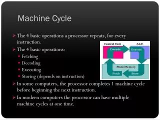
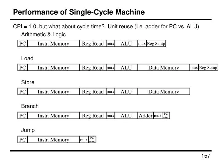
PC Instr. Memory Reg Read mux ALU Adder mux PCsetup PC Instr. Memory Reg Read mux ALU Data Memory PC Instr. Memory Reg Read mux ALU mux Reg Setup PC Instr. Memory mux PCsetup PC Instr. Memory Reg Read mux ALU Data Memory mux Reg Setup Performance of Single-Cycle Machine • CPI = 1.0, but what about cycle time? Unit reuse (I.e. adder for PC vs. ALU) • Arithmetic & Logic • Load • Store • Branch • Jump
storage element storage element Acyclic Combinational Logic (A) Acyclic Combinational Logic storage element Acyclic Combinational Logic (B) storage element storage element Reducing Cycle Time • Cut combinational dependency graph and insert register / latch • Do same work in two fast cycles, rather than one slow one
PC Data Memory Instr. Memory Register File Register File Multicycle Processor Overview • Divide datapath into multiple cycles IF Instruction Fetch RF Register Fetch EX Execute MEM Data Memory WB Writeback
Multicycle Processor Changes • Only one memory • Shared between instructions and data • Only one ALU/adder • Use ALU for instructions & PC computations • Add registers to datapath • IR: instruction register • MDR: Memory Data Register • A & B: Values read from register file • ALUout: Output of ALU
Cycle 1: Instruction Fetch • Put the instruction to execute into the Instruction Register (IR) • RTL: • Set the PC to the next instruction (ignore branches) • RTL:
IR Rs Rt Rd Imm16 WrEn Addr Dout Memory Din Aw Ab Aa Da Registers Dw WrEn Db SignExtnd PC <<2 MDR ALUOut B A Cycle 1 Datapath
Cycle 2: Instruction Decode, Register Fetch • Store the two GPR operands into registers A and B • RTL: • Compute Branch Target (in case it’s a branch operation, won’t have time later) • RTL:
IR Rs Rt Rd Imm16 WrEn Addr Dout Memory Din Aw Ab Aa Da Registers Dw WrEn Db SignExtnd PC <<2 MDR ALUOut B A Cycle 1+2 Datapath 4
Cycle 3 (Branch) • Branch (Beq) – Branch address in ALUout. Set PC to branch address if A==B • RTL:
IR Rs Rt Rd Imm16 WrEn Addr Dout Memory Din Aw Ab Aa Da Registers Dw WrEn Db SignExtnd PC <<2 MDR ALUOut B A Branch Datapath 4
Cycle 3-4 (Add, Subtract) • Cycle 3: compute function in ALU, operands in A & B. Store in ALUout • RTL: • Cycle 4: Write value from ALUout to destination register • RTL:
IR Rs Rt Rd Imm16 WrEn Addr Dout Memory Din Aw Ab Aa Da Registers Dw WrEn Db SignExtnd PC <<2 MDR ALUOut B A Branch, R-Type Datapath 4
Cycle 3-4 (Store) • Cycle 3: compute address from operand A and IR[15-0], put into ALUout • RTL: • Cycle 4: Store value from operand B to address specified in ALUout • RTL:
IR Rs Rt Rd Imm16 WrEn Addr Dout Memory Din Aw Ab Aa Da Registers Dw WrEn Db SignExtnd PC <<2 MDR ALUOut B A Branch, R-Type, Store Datapath 4
Cycle 3-5 (Load) • Cycle 3: compute address from operand A and IR[15-0], put into ALUout • RTL: • Cycle 4: Load value from address specified in ALUout to MDR • RTL: • Cycle 5: Write value from MDR to destination register • RTL:
IR Rs Rt Rd Imm16 WrEn Addr Dout Memory Din Aw Ab Aa Da Registers Dw WrEn Db SignExtnd PC <<2 MDR ALUOut B A Multicycle Processor Datapath 4
Multicycle Processor Control • Need to control data path to perform required operations • Multiple cycles w/different control values each cycle, so control is an FSM. • Cycle 1: IR = Mem[PC]; PC = PC + 4 • Cycle 2: A = Reg[RS]; B = Reg[Rt]; • ALUOut = PC + (Sign-extend(Imm16)<<2) • Cycle 3 Branch: Zero = (A-B); If (zero) PC = ALUout • Cycle 3 R-Type: ALUout = A op B • Cycle 4 R-Type: Reg[Rd] = ALUout • Cycle 3 Store: ALUout = A + sign-extend(Imm16) • Cycle 4 Store: Mem[ALUout] = B • Cycle 3 Load: ALUout = A + sign-extend(Imm16) • Cycle 4 Load: MDR = Mem[ALUout] • Cycle 5 Load: Reg[Rt] = MDR
Control FSM • Opcodes: LW 35, SW 43, BEQ 4, add/sub 0
IR Rs Rt Rd Imm16 WrEn Addr Dout Memory Din Aw Ab Aa Da Registers Dw WrEn Db SignExtnd PC <<2 MDR ALUOut B A Datapath Control Signals 4
Multicycle Datapath Control 1:IR = Mem[PC]PC = PC + 4 2:A = Reg[Rs]B = Reg[Rt]ALUOut = PC + (SE(imm16)<<2) 3Br:Zero = (A-B)If (zero) PC = ALUout 3Rt:ALUout = A op B 4Rt:Reg[Rd] = ALUout 3St:ALUout = A + SE(Imm16) 4St:Mem[ALUout] = B 3Lo:ALUout = A + SE(Imm16) 4Lo:MDR = Mem[ALUout] 5Lo:Reg[Rt] = MDR
IR Rs Rt Rd Imm16 WrEn Addr Dout Memory Din Aw Ab Aa Da Registers Dw WrEn Db SignExtnd PC <<2 MDR ALUOut B A Cycle 1 Control • IR = Mem[PC]; PC = PC + 4 PCSrc MemIn ALUOp Dst ALUSrcA PC_WE IR_WE Mem_WE 4 ALUSrcB Reg_WE RegIn
IR Rs Rt Rd Imm16 WrEn Addr Dout Memory Din Aw Ab Aa Da Registers Dw WrEn Db SignExtnd PC <<2 MDR ALUOut B A Cycle 2 Control • A=Reg[Rs]; B=Reg[Rt]; ALUOut = PC+(Sign-extend(Imm16)<<2) PCSrc MemIn ALUOp Dst ALUSrcA PC_WE IR_WE Mem_WE 4 ALUSrcB Reg_WE RegIn
IR Rs Rt Rd Imm16 WrEn Addr Dout Memory Din Aw Ab Aa Da Registers Dw WrEn Db SignExtnd PC <<2 MDR ALUOut B A Cycle 3 (Branch) Control • Zero = (A-B); If (zero) PC = ALUout PCSrc MemIn ALUOp Dst ALUSrcA PC_WE IR_WE Mem_WE 4 ALUSrcB Reg_WE RegIn
IR Rs Rt Rd Imm16 WrEn Addr Dout Memory Din Aw Ab Aa Da Registers Dw WrEn Db SignExtnd PC <<2 MDR ALUOut B A Cycle 3 (R-Type) Control • ALUout = A op B PCSrc MemIn ALUOp Dst ALUSrcA PC_WE IR_WE Mem_WE 4 ALUSrcB Reg_WE RegIn
IR Rs Rt Rd Imm16 WrEn Addr Dout Memory Din Aw Ab Aa Da Registers Dw WrEn Db SignExtnd PC <<2 MDR ALUOut B A Cycle 4 (R-Type) Control • Reg[Rd] = ALUout PCSrc MemIn ALUOp Dst ALUSrcA PC_WE IR_WE Mem_WE 4 ALUSrcB Reg_WE RegIn
IR Rs Rt Rd Imm16 WrEn Addr Dout Memory Din Aw Ab Aa Da Registers Dw WrEn Db SignExtnd PC <<2 MDR ALUOut B A Cycle 3 (Store) Control • ALUout = A + sign-extend(Imm16) PCSrc MemIn ALUOp Dst ALUSrcA PC_WE IR_WE Mem_WE 4 ALUSrcB Reg_WE RegIn
IR Rs Rt Rd Imm16 WrEn Addr Dout Memory Din Aw Ab Aa Da Registers Dw WrEn Db SignExtnd PC <<2 MDR ALUOut B A Cycle 4 (Store) Control • Mem[ALUout] = B PCSrc MemIn ALUOp Dst ALUSrcA PC_WE IR_WE Mem_WE 4 ALUSrcB Reg_WE RegIn
IR Rs Rt Rd Imm16 WrEn Addr Dout Memory Din Aw Ab Aa Da Registers Dw WrEn Db SignExtnd PC <<2 MDR ALUOut B A Cycle 3 (Load) Control • ALUout = A + sign-extend(Imm16) PCSrc MemIn ALUOp Dst ALUSrcA PC_WE IR_WE Mem_WE 4 ALUSrcB Reg_WE RegIn
IR Rs Rt Rd Imm16 WrEn Addr Dout Memory Din Aw Ab Aa Da Registers Dw WrEn Db SignExtnd PC <<2 MDR ALUOut B A Cycle 4 (Load) Control • MDR = Mem[ALUout] PCSrc MemIn ALUOp Dst ALUSrcA PC_WE IR_WE Mem_WE 4 ALUSrcB Reg_WE RegIn
IR Rs Rt Rd Imm16 WrEn Addr Dout Memory Din Aw Ab Aa Da Registers Dw WrEn Db SignExtnd PC <<2 MDR ALUOut B A Cycle 5 (Load) Control • Reg[Rt] = MDR PCSrc MemIn ALUOp Dst ALUSrcA PC_WE IR_WE Mem_WE 4 ALUSrcB Reg_WE RegIn
System Exception Handler user program return from exception Advanced: Exceptions • Exception = unusual event in processor • Arithmetic overflow, divide by zero, … • Call an undefined instruction • Hardware failure • I/O device request (called an “interrupt”) • Approaches • Make software test for exceptional events when they may occur (“polling”) • Have hardware detect these events & react: • Save state (Exception Program Counter, protect the GPRs, note cause) • Call Operating System • If (undef_instr) PC = C0000000 • If (overflow) PC = C0000020 • If (I/O) PC = C0000040 • … Exception:
Advanced: Exceptions (cont.) IFetch Decode Op = = 35 Op = = 4 Op = = 0 Op = = 43 Branch R-type1 Store 1 Load 1 R-type2 Store 2 Load 2 Exception: EPC = PC PC = ExcepHandler Set Cause Load 3
Multicycle CPI • Compute the CPI of the machine, given the frequencies specified
Multicycle Summary • By splitting the single-cycle datapath up we achieve: