Download
1 / 11
120 likes | 377 Vues
Flip-Flops and Related Devices. Wen-Hung Liao, Ph.D. Objectives. Construct and analyze the operation of a latch flip-flop made from NAND or NOR gates. Describe the difference between synchronous and asynchronous systems. Understand the operation of edge-triggered flip-flops.

E N D
Flip-Flops and Related Devices Wen-Hung Liao, Ph.D.
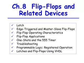
Objectives • Construct and analyze the operation of a latch flip-flop made from NAND or NOR gates. • Describe the difference between synchronous and asynchronous systems. • Understand the operation of edge-triggered flip-flops. • Analyze and apply the various flip-flop timing parameters specified by the manufacturers. • Understand the major differences between parallel and serial data transfers. • Draw the output timing waveforms of several types of flip-flops in response to a set of input signals.
Objectives • Recognize the various IEEE/ANSI flip-flop symbols. • Use state transition diagrams to describe counter operation. • Use flip-flops in synchronization circuits. • Connect shift registers as data transfer circuits. • Employ flip-flops as frequency-division and counting circuits. • Understand the typical characteristics of Schmitt triggers. • Apply two different types of one-shots in circuit design. • Design a free-running oscillator using a 555 timer. • Recognize and predict the effects of clock skew on synchronous circuits. • Troubleshoot various types of flip-flop circuits. • Program a PLD using CUPL's state transition format for circuit description.
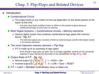
Introduction • General digital system diagram: consists of combinational logic gates and memory elements. • The most important memory element is the flip-flop, which is made up of an assembly of logic gates. • General flip-flop symbol (Figure 5.2) • Q: normal FF output, Q’:inverted FF output • SET/CLEAR(RESET) input
NAND Gate Latch • Constructed using two NAND gates. • Active-LOW Q
Applications • Example 5-1 shows that the latch output remembers the last input that was activated and will not change states until the opposite input is activated. • Example 5-2: switch debouncing circuit
NOR Gate Latch • Constructed using two NOR gates. • Active-HIGH
Flip-Flop State on Power-up • Do not know the starting state of a flip-flop’s output.
Clock Signals and Clocked FFs • Asynchronous system: outputs of logic circuit can change state any time one or more of the inputs change. More difficult to design and troubleshoot. • In synchronous systems, the exact times at which any output change change states are determined by a signal commonly called the clock.
Clock • System outputs can change states only when the clock makes a transition. • Positive-going transition • Negative-going transition • Most digital systems are principally synchronous.
Clocked Flip-Flops • Controlled inputs + CLK • Setup and Hold times • Clocked S-C Flip-Flop • Clocked J-K Flip-Flop • Clocked D Flip-Flop