Download
1 / 22
220 likes | 413 Vues
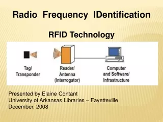
Compact Radio Frequency Technology for Applications in Cargo and Global Security. Graeme Burt Lancaster University, Cockcroft Institute, Security Lancaster. Cargo Screening Accelerators. Aircraft ULD or pallets are too large for baggage scanners and too small for cargo scanners.

E N D
Compact Radio Frequency Technology for Applications in Cargo and Global Security Graeme Burt Lancaster University, Cockcroft Institute, Security Lancaster
Cargo Screening Accelerators Aircraft ULD or pallets are too large for baggage scanners and too small for cargo scanners. Currently searched by hand. Luggage Scanning requires a few tens to hundreds keV. This can be delivered by traditional X-ray tubes up to 450 keV. Ideal energy is around 1-2 MeV but no current source available. Truck or shipping cargo is larger requires ~6 MeV. Industrial linacs can provide this.
CLASP Ph-I Collaboration Team • Lancaster University: • Graeme Burt (Project Leader) • Praveen Ambattu (Linac) • Chris Lingwood (Linac) • Tom Abram (Mechanical) • Mike Jenkins (Linac) • STFC, ASTeC Daresbury Lab: • Ian Burrows (Mechanical Eng.) • Clive Hill (Mechanical) • Peter Corlett (Project Manager) • Andrew Goulden (Cooling Sys.) • Paul Hindley (Installation) • Peter McIntosh (ASTeC PI) • Keith Middleman (Vacuum) • Rob Smith (Beam Diagnostics) • Chris White (Electrical Eng.) • Trevor Hartnett (Electrical) • Steve Griffith (electrical)
X-band Linac schematic DC Electron Gun e2V X-ray Target Buncher and Accelerating Structure (1 MeV) CI Proposal Scope Phase-I Magnetron e2V (9.3 GHz, 1.2 MW, 100-400 Hz) Dynamic switching of amplitude and phase pulse-to-pulse) Automated Control System (Energy, rep-rate, dose) CI-SAC Dec 2011
Why X-band? • For a mobile linac mounted on a robotic arm the weight of the linac is critical. • While the linac isn’t very big or heavy the shielding is. • X-band means that the shielding diameter is much less. • Area of shielding is given by • (2rcavtshield + tshield2)p • Availability of 9.3 GHz magnetrons
CLIC crab Cavity • Lancaster has some experience in X-band from the CLIC crab cavities. • A prototype of this cavity has recently been manufactured and tuned at CERN and is awaiting a testing slot in XBox2.
Linac options • Side coupled pi/2-mode • pi/2 >> frequency stability especially in the presence of large number of cells • Shunt impedance comparable to pi-mode • Large transverse size due to coupling cells • Bi-periodic pi/2-mode • pi/2 >> frequency stability especially in the presence of large number of cells • Shunt impedance less than side-coupled structures pi-mode • Hard to tune coupling cells and are sensitive to brazing tolerances
1 MeVLinac Design 5 mm beampipe diameter 3.5 mm iris thickness 1 mm coupling cell thickness
Beam Tracking Analysis • Particle Tracking initially performed in ASTRA. • Collaboration with Tech-X UK to verify Linac electron beam capture and tracking. • Using VORPAL code to validate PIC transport. • Good comparison was found between both methods. http://www.txcorp.com/products/VORPAL/
Linac Fabrication • Fabrication commissioned with UK industry: • Shakespeare Engineering, Ltd • Geometric tolerances of 10 m required. • Diamond machining and vacuum brazing processes employed. http://www.shakespeareengineering.co.uk/
Cavity Tuning Ideal profile Structure was found to have poor matching and field flatness. Low beta cells were further off frequency than could be tuned.
17 keV Electron Gun from E2v A 17 keV electron gun was specially designed for this project from a TWT gun. The gun was modified to provide 200 mA with a 1mm spot size. Gun has been successfully tested at Daresbury. http://www.e2v.com/ Substantial ringing is found on the ICT due to EM interference from pulse operation.
Magnetron Testing E2V engineers acceptance tested the magnetron at Daresbury. Maximum power achieved ~ 1.1 MW but not sustainable due to arcs. Operating at long pulse lengths (4 us) and high power (>1 MW) results in significant arcing within the magnetron.
Diagnostics Line • In order to fully diagnose the beam from the linac we have a diagnostics line fitted to the output. • We have a motorised section which can either provide a slit, a screen, a tungsten target or vacuum.
Imaging and testing • Conveyor system set up in the linac area to perform full system characterisation in a realistic environment. • Detector system developed by a local scanning company. Good quality full scale imaging requires dose of at least 0.03 Gy/min @ 1m @ 100Hz
Linac Testing So far the linac has produced a 750 keV, 1 mA beam as measured on the spectrometer and Faraday cup/ICT at the end of the diagnostics line (probably large beam loss prior to this). This is limited by the cavity being slightly out of tolerance affecting the fields.
Learning Curve • Improvements to Mk II design • Less rounding on equator to allow less stiffness, more tuning range • Re-entrant first cell to reduce stiffness, increase tuning range • Larger cell-to-cell coupling • Longitudinal cooling pipes, more room for tuning pins • Move coupler to centre cell
Modified structure New 490 MHz wide Contract placed with Comeb Mode 8 Old 60 MHz wide We have developed a new X-band structure with much greater cell-to-cell coupling to increase tolerances. Simple structure design with no slots to help tolerances (low fields and low voltage make this acceptable)
Harmonic W-band Klystron There is also interest in millimetre wave and THz scanning of personnel. For this application we have been developing a 105 GHz Klystron. To avoid issues with poor scaling of Klystrons to high frequencies we use a 3rd harmonic output cavity. 105 GHz output cavity 35 GHz input and intermediate cavities
Mm-wave upconverter To increase the size of the output cavity such that it could be made from conventional machining we use a higher order mode cavity (TM020-like) Output coupler 94GHz Input coupler 31GHz
Harmonic W-band Klystron • Structure casted in Silver from a 3D printed hard plastic mould. • Allows better material quality, tolerances and surface roughness than direct 3D printing in metal. • Initial prototypes are promising.
Conclusion • A strong UK collaborative team has been formulated to successfully demonstrate a working system solution. • Challenging requirement to develop and demonstrate a gun, magnetron and 1 MeVlinac system within 18 months. • Major development successes: • An optimised 17 keV, high peak current electron gun has been designed, fabricated and activated. • A highly compact combined buncher/accelerating structure has been designed. • High precision fabrication has been demonstrated for the complex linac geometry. • The linac system has been assembled and has so far produced 750 keV electron beam at 1 mA. • Also developing high frequency sources for imaging