Download
1 / 35
350 likes | 541 Vues
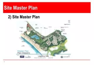
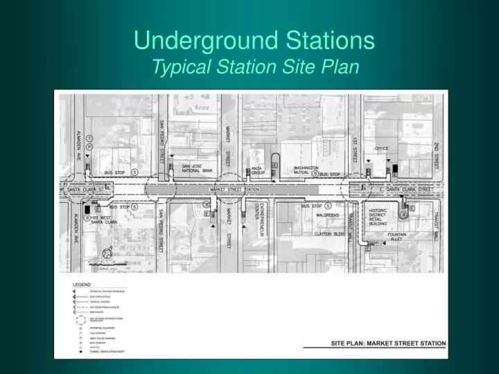
Underground Stations Typical Station Site Plan. Underground Stations Ground Conditions: Key Issues. Design Criteria for Shoring System. 1. Base Stability and Deformations 2. Stability Under Hydrostatic Uplift Pressures 3. Lateral Pressures for Wall Design

E N D
Design Criteria for Shoring System 1. Base Stability and Deformations 2. Stability Under Hydrostatic Uplift Pressures 3. Lateral Pressures for Wall Design • Lateral Pressures for Design of Bracing (Prelim Design) • Soil Structure Interaction Analysis (Final Design)
Important Sources of Ground Deformations • Installation of Soldier Piles • Construction of Diaphragm Walls/Soil-Cement Walls • Excavation (Including removal of struts) • Jet Grouting • Installation of Pile Foundations • Dewatering • Vibrations (Steel sheetpiles or foundation pile driving) • Extraction of Old Piles
Howard Street Closed Mission Street Concrete Decking The Embarcadero Northbound Southbound Excavation Adjacent to BuildingMuni Metro Turnback
Settlements of Buildings Caused by ExcavationsMuni Metro Turnback
Deformations Caused by Jet Grouting and Excavation SPTC Walls Islais Creek Contract E
Lateral Deformations Caused by Excavation and Removal of Struts (a) Inclinometer No. E-87;Indiana Street Segment (b) Inclinometer No. N-120; Overflow Structure
Risk Management and Cost Containment • Design shoring for deformation control • Complete shoring design to eliminate risk that contractors may underbid the shoring and then look for excuses to claim extra for changed conditions • Define subsurface conditions to a level that illustrates clearly the expected variability at the site. Comprehensive Geotechnical Investigation is essential
Risk Management and Cost Containment • Perform detailed evaluation of impacts on adjacent buildings and evaluate the need for strengthening or underpinning of existing structures • Develop preliminary plans to deal with potentially unexpected adverse impacts on adjacent structures; include a budget contingency
Risk Management and Cost Containment • Provide for a comprehensive monitoring program to evaluate potential impacts on adjacent structures. Keep the instrumentation and the monitoring under the control of the designer and VTA
Risk Management and Cost Containment • Use soil-cement walls to achieve economy and safety • Higher production rates by a factor of 2 • Lower cost per sq foot • Incorporate soil-cement wall as part of permanent structure • Better control of spoils • Lower risk of accidental spill in the traffic lanes
Conceptual Design for Incorporating Temporary Soil-Cement Shoring Into Permanent Wall of Box Structure
Risk Management and Cost Containment • Minimize interfaces between designers and contractors • Keep design of shoring under station contract • Have one contractor responsible for all excavations and shoring
Risk Management and Cost Containment • Evaluate instrumentation results promptly to detect the onset of difficulties as early as possible, and take steps to minimize problems • Avoid underpinning to the extent possible • Have proactive plan to strengthen buildings that can not tolerate the expected settlement • Avoid dewatering
1 Reasons for Including the Station Shells in Stations Contract • Minimizes interfaces between designers • Additional and significant excavations are required for entrances. Need to have coordinated design to minimize impacts on adjacent buildings. i.e. Consideration of cumulative effects • Provide single point of responsibility for design and performance – Avoid mistakes and duplication of effort • Avoid division of responsibility for performance of the shoring after the excavation is completed
2 Reasons for Including the Station Shells in Stations Contract • Minimizes interfaces between designers (contd) • Avoid having the tunnel designers to design the base slab of the station which is essential for pulling the tunneling machine through the station • Coordinate shoring design with design of openings in the station shells for entrances (avoid having to restrut the excavation to accommodate the openings)
3 Reasons for Including the Station Shells in Stations Contract • Maintain Construction of all shoring under one contract • Construct the shoring for the entrances and stations under a single contract for more efficient coordination – Avoid Division of Responsibility • Have the same contractor who installs the shoring to be responsible for strut removal during construction of the box structure – Avoid Division of Responsibility
4 Reasons for Including the Station Shells in Stations Contract • Minimize the time that the excavation remains open after completion of excavation • Flexibility to construct the base slabs in advance of tunnel break through the station. • Minimizes overall risk
Stress History ProfilesMarket Street and Civic Plaza Stations
Empirical Charts Settlements Caused by ExcavationStiff Clays
Deformations Caused by Construction of Slurry Walls 0 10 20 30 SOIL SETTLEMENT (mm) DEPTH IN METERS 40 50 60
Lateral Deformation Caused by Slurry Wall ConstructionMuni Metro Turnback
Howard Street ExcavationsMuni Metro Turnback
Soil Strength CharacteristicsMarket Street Station, San Jose
Use of Jet Grouting for Control of Deformations Comparison of Conventional “Stiff” System with New Shoring Concept
Lateral Deformations Caused by Jet Grouting (b) Inclinometer No. N-76;Overflow Structure (a) Inclinometer No. E-155;Indiana Street Segment
Risk Management and Cost Containment • Work under decking to maintain traffic flowing on Santa Clara Street • Construct soil-cement solidified zones behind the end walls of the box to facilitate tunnel breakthrough. Minimize interface with tunnel designer and tunneling contractor