Download
1 / 40
620 likes | 1.26k Vues
X-ray lithography (XRL). Overview and resolution limit. X-ray source ( electron impact and synchrotron radiation). X-ray absorption and scattering. X-ray lithography resist (PMMA and SU-8). X-ray lithography mask (absorber on membrane). LIGA process (for high aspect ratio metal structure).

E N D
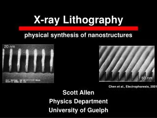
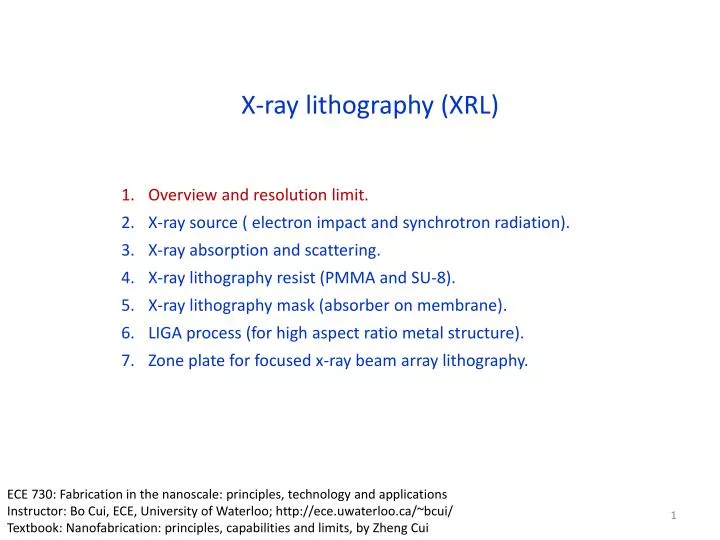
X-ray lithography (XRL) Overview and resolution limit. X-ray source ( electron impact and synchrotron radiation). X-ray absorption and scattering. X-ray lithography resist (PMMA and SU-8). X-ray lithography mask (absorber on membrane). LIGA process (for high aspect ratio metal structure). Zone plate for focused x-ray beam array lithography. ECE 730: Fabrication in the nanoscale: principles, technology and applications Instructor: Bo Cui, ECE, University of Waterloo; http://ece.uwaterloo.ca/~bcui/ Textbook: Nanofabrication: principles, capabilities and limits, by Zheng Cui
X-ray lithography history D. L. Spears and H. I. Smith, “High resolution pattern replication using soft x-rays”, Electronic Letters, 8, 102 (1972). H. I. Smith (MIT)
Microwave Cell phone, PCS FM AM X-ray What is X-ray? Wilhelm Conrad Roentgen (1845-1923) • Roentgen discovered an unknown ray in 1895 (X-ray) that can cause barium platinocyanide-coated screen to glow. • He won the first Nobel prize in physics in 1901.
Setup of proximity x-ray lithography Mask is made of absorber (Au…) on membrane (Si3N4…)
X-ray lithography advantages • Wavelength: 10’s nm(soft x-rays) down to 1Å (subatomic). • Little diffraction effects when using such small . • No backscatter or reflections: very fine features with verticalsidewalls. • Very large depth of focus: wafer with non-flat surface is OK. • Simpler (in principle) than optical or e-beam lithography: no complex optics (don’t really have x-ray optics now). • All that needed is an x-ray source and an x-ray mask.
X-ray lithography limits • 1X mask technology because refractive index for all materials is (almost) absolutely 1.0 (no lens for demagnification). (4 for DUV lithography, mask easier to make) • X-ray mask difficult to fabricate with many issues: fragile, defects, aspect ratio, bending due to heating. • Strong, stable, collimated, single frequency x-ray sources are hard to find. X-rays produced in synchrotrons fit this criteria, but with high cost and huge size. • Resolution is still limited by Fresnel diffraction and scattering of secondary electrons in the resist. • Typical resist is insensitive, need long time to expose. w h Aspect ratio=pattern height/width=h/w.
Comparison to other lithographies E-beam lithography (scattering, proximity effect) Photolithography, diffraction limits resolution X-ray lithography, little diffraction, high depth of focus Ion beam lithography, low penetration depth (very thin resist) The physics of microfabrication, I. Brodie and J. J. Murray, Plenum Press, 1982
X-ray lithography: resolution limit due to diffraction • Precise gap must be maintained: too close will damage membrane mask, too far reduce resolution. • Although is very small, diffraction still present. • Resolution limit due to diffraction R=3/2[(g+t/2)]1/2, g: gap; t: resist thickness. • (This is the same resolution equation as for photolithography) • E.g. 100nm feature size requires =1nm, g=4.4m (assume t<<g). Cerrina, J Phys D, 2000
Resolution limit due to secondary effects • Secondary effects: • X-ray fluorescence of mask and substrate that exposes resist. • Lateral diffusion of photoelectron and Auger electron. • Thermal induced mask or resist motion or distortion. • Non-vertical sidewall of the Au absorber on mask. It is found that the Auger electron (low energy) is 10 more efficient to expose resist than photo-electron (high energy); and the Auger electron diffuse only <5nm. Therefore, the photo-electron is not that important in determining the final resolution, and high resolution (<20nm) can be achieved provided such a mask can be made (VERY difficult).
X-ray absorption: photoelectric absorption dominates at <10keV The picture below is similar to electron bombardment x-ray source (see slide #13), where core electron is kicked off by an incident electron. Here it is kicked off by x-ray. In the relaxation process, the lower energy photon is a fluorescent x-ray, while the lower energy electron is an Auger electron. (fluorescent x-ray) Photon (x-ray) (Auger electron) 1. A high energy x-ray photon impinges on an atom Electron (low energy) X-ray Photon (fluorescent x-ray) atom 3. The atom relaxes toits ground state byemission of a photon or electron Photo-electron 2. An inner-shell (here K-shell) electron (photo-electron) is knocked out of the atom. Auger-electron Electron (Auger electron, emitted from M-shell) k is the energy level of the K-shell…
High resolution resist structures by x-ray lithography 50nm lines 150nm lines R. Waser (ed.), Nanoelectronics and Information Technology
X-ray lithography (XRL) Overview and resolution limit. X-ray source ( electron impact and synchrotron radiation). X-ray absorption and scattering. X-ray lithography resist (PMMA and SU-8). X-ray lithography mask (absorber on membrane). LIGA process (for high aspect ratio metal structure). Zone plate for focused x-ray beam array lithography.
Laser produced plasma x-ray source X-ray source and their irradiation power (impact) metaltape high powerlaser • Same idea as laser produced plasma (LPP) EUV source, but shorter wavelength (a few nm). • High power-density laser pulses generate a hot and dense plasma, which emits x-rays when free electrons recombine with ions, or bond electrons jump to a lower energy level. • More complicated than electron bombardment source, less powerful than synchrotron radiation.
X-ray generation by electron impact (bombardment) e1 In atomic physics, K denotes the shell/orbit with n=1 (innermost shell), L for n=2, M for n=3, N for n=4… The energy level for atom with atomic number Z is given by: E=-13.56 Z2/n2 (eV) X-ray e1 e2 (photo-electron) When electron jumps from L to K-shell, it either emits x-ray (as shown in the figure), or gives its energy to an outer-shell electron that escapes subsequently (Auger electron, not shown). For K line: Here (Z-1) instead of Z due to screening effect of the other electron in n=1 level. More generally, (Z-1) should be replaced by (Z-), with accounting for the screening effect.
Electron impact: sealed tube x-ray source (point source) • Developed by Coolidge (at GE) around 1912. • Electron accelerated at high energy to the anode. • Low power, tuned to maximize for narrow emission range (for example, Mg or Cu K). • For material characterization by x-ray diffraction and medical imaging X-ray e Hot filament emits electrons
Electron impact: rotating anode source -50kV H2O inand out Refractory anode rotating at 6000rpm Rotating anode source: Same principle as sealed tube x-ray source, but with much higher power due to greater thermal capacity – cooling wafer, rotating, refractory metal.
Synchrotron radiation x-ray source: the choice for x-ray lithography Storage Ring Shield Wall Synchrotron radiation (SR): • Electromagnetic radiation (light) emitted from electrons moving with relativistic velocities. • First observed in 1947 from a 70MeV electron accelerator at GE. • In earlier times, it was just considered as waste product, limiting accelerator performance. • However, other researchers soon realized that SR was the brightest source of infrared, ultraviolet, and x-rays, very useful for studying matter on the scale of atoms and molecules. • Irradiation is highly polarized and pulsed (e.g. nanosecond pulse). • Observer sees only a small portion of electron trajectory. The pulse length is thus the difference in time it takes an electron and a photon to cover this distance on the circle.
How synchrotron radiation works? Bending magnet: For normal-conductive B1.5 Tesla. “C” shaped allowing radiation to exit Straight line Bend and emit when passing a magnet Accelerated here • Typically a low-energy accelerator injects “bunches” of electrons into a storage ring; the charged particle are in pico-second pulses spaced nanoseconds apart. • Acceleration is produced by an alternating (RF – radio frequency) electric field that is in synchronism with orbital frequency. • A broad continuum of radiation is emitted by each bunch when it changes direction, with the median (or “critical”) wavelength given by
Radiation is due to charge acceleration Synchrotron radiation: electromagnetic radiation emitted when charged particles are radially accelerated (move on a curved path) Antenna: electrons accelerating by running up and down in a radio antenna emit radio waves (long wavelength electromagnetic waves Radial acceleration a=v2/R (v is speed, R is radius) Both cases are manifestation of the same physical phenomenon: Charged particles radiate (only) when accelerated.
Cone aperture ~ 1/g Synchrotron radiation angular distribution p: power a: acceleration : spherical angle No radiation along acceleration direction. Strongest radiation at perpendicular direction.
Bending Magnet Spectrum of synchrotron radiation (bending magnet) (critical energy) 1.24nm Electron rest energy=mc2=(9.110-31)(3108)2=8.1910-14J=0.511MeV (very small). Total electron energy=mc2, with =1/(1-v2/c2)1/2. For 1.0GeV energy, =1000/0.511=1957, so v/c=0.99999987, indeed v is very close to c.
Particle trajectory “Wiggler or undulator” radiation • For bending magnet radiation, electrons are accelerated/bended by uniform magnetic field (B along +z direction, circular electron trajectory). • By putting an array of permanent magnets like below, magnetic field alternates up (+z direction) and down (-z), causing the particles to bend back and forth along the horizontal plane. • At each bend, the electrons emit synchrotron radiation in the x-ray part of the spectrum. (positive electron)
Undulator radiation: Doppler shift to nm wavelength Synchrotron radiation from relativistic electrons You can try to understand the following calculation if interested. It won’t be included in exams. In the frame moving with the electron, electron “sees” a periodic magnet structure moving toward it with a relativistically contracted period ’=u/ (u is magnet period, 1/(1-2)1/2, v/c) The frequency of this emitted radiation is f’=c/’=c/u. To the observer, the relativistic form of Doppler frequency formula is: f=f’/((1-))=c/(u(1-))22c/u. (for 1, 1-1/22) So the observed wavelength is: =c/f= u /22. E.g, for 1.9GeV, =1900/0.511=3718; with u =5cm, gives =1.8nm (x-ray).
Advantages of synchrotrons for X-ray lithography • Extremely high intensity. • Extremely high brilliance - small effective source size situated a long distance from the experimental station. • Very low divergence out of the plane of storage ring. • Tunable, specific energies can be chosen. • Highly polarized and short pulses. • It offers many characteristics of visible lasers but into the x-ray regime: partial coherence, high stability.
Comparison of brightness ( ) ALS: Advanced Light Source @ Berkeley @LBNL Rontgen (electron impact source) Slides modified from lecture by Fernando Sannibale Advanced Light Source Accelerator Physics Group Ernest Orlando Lawrence Berkeley National Laboratory
Wavelength selection: mono-chromator by x-ray diffraction This is the same idea as x-ray diffraction for characterizing materials. It works only for high energy/short wavelength x-ray, since = 2dsin/n < 2d, d1Å. n=1, 2, 3… d is crystal lattice constant
X-ray lithography (XRL) Overview and resolution limit. X-ray source ( electron impact and synchrotron radiation). X-ray absorption and scattering. X-ray lithography resist (PMMA and SU-8). X-ray lithography mask (absorber on membrane). LIGA process (for high aspect ratio metal structure). Zone plate for focused x-ray beam array lithography.
X-ray absorption / attenuation characteristic TARGET Intensity I0 Intensity I X-ray : absorption coefficient 1/ : attenuation length (Compton) t (Rayleigh) In addition to photoelectric absorption (producing photoelectrons and characteristic x-rays or Auger electrons), the original x-rays may be scattered by electrons. There are two kinds of scattering: coherent (Rayleigh, no energy loss) and incoherent (Compton).
X-ray scattering Coherent Coherent scattering: happens when x-ray “collides” with an atom and deviates without a loss in energy. An electron in an alternating electromagnetic field (x-ray) will oscillate at the same frequency and emit in all directions. This is useful for understanding x-ray diffraction (each atom is a new x-ray point source). Incoherent scattering: incident x-ray loses some of its energy to the scattering electron. As total energy (=hc/) is preserved, the wavelength of the scattered photon increases by: (in Å) (Here 0.0243=h/mec, h=6.6310-34 is Plank’s constant, me=9.110-31kg is electron’s mass) Incoherent (Compton scattering)
X-ray absorption: photoelectric absorption dominates at <10keV The picture below is similar to electron bombardment x-ray source (see slide #14), where core electron is kicked off by an incident electron. Here it is kicked off by x-ray (the incident x-ray is absorbed/lost). In the relaxation process, the lower (than incident x-ray photon) energy photon is a fluorescent x-ray, while the lower energy electron is an Auger electron. (fluorescent x-ray) Photon (x-ray) (Auger electron) 1. A high energy x-ray photon impinges on an atom Electron (low energy) X-ray Photon (fluorescent x-ray) atom 3. The atom relaxes toits ground state byemission of a photon or electron Photo-electron 2. An inner-shell (here K-shell) electron (photo-electron) is knocked out of the atom. Auger-electron Electron (Auger electron, emitted from M-shell) k is the energy level of the K-shell…
X-ray generation by electron impact (bombardment) e1 In atomic physics, K denotes the shell/orbit with n=1 (innermost shell), L for n=2, M for n=3, N for n=4… The energy level for atom with atomic number Z is given by: E=-13.56 Z2/n2 (eV) X-ray e1 e2 (photo-electron) When electron jumps from L to K-shell, it either emits x-ray (as shown in the figure), or gives its energy to an outer-shell electron that escapes subsequently (Auger electron, not shown). For K line: Here (Z-1) instead of Z due to screening effect of the other electron in n=1 level. More generally, (Z-1) should be replaced by (Z-), with accounting for the screening effect.
X-ray lithography (XRL) Overview and resolution limit. X-ray source ( electron impact and synchrotron radiation). X-ray absorption and scattering. X-ray lithography resist (PMMA and SU-8). X-ray lithography mask (absorber on membrane). LIGA process (for high aspect ratio metal structure). Zone plate for focused x-ray beam array lithography.
X-ray interaction with resist • Absorption of x-ray does not lead directly to resist modification. • Photoelectrons and Auger electrons are responsible for resist modification. • Therefore, x-ray lithography resist is similar to that for e-beam lithography. • That is, any e-beam lithography resist can also be used as x-ray lithography resist. • In general, high energy x-rays (e.g. =0.3-5Å) do not interact strongly with materials, so very low absorption. • The good news: x-ray resist will be uniformly illuminated (top to bottom) for not-so-thick resist. • The bad news: x-ray masks will be hard to make opaque (need many m Au). • The worse news: powerful x-ray sources are needed (most energy just pass through without exposing the resist). • To reduce exposure time substantially, one can use chemically amplified resist (SU-8) having high sensitivity.
X-ray absorption by PMMA resist X-ray absorption of PMMA Transmission of PMMA Linear absorption coefficient (1/m) Transmission of PMMA sheets of different thickness 1.24nm Photon energy (eV) Photon energy (eV) Attenuation length 1/ (penetration depth) For the same resist thickness: Higher energy less absorption, more uniform dose profile throughout the thickness, but low resist sensitivity and needs longer exposure time. So tradeoff must be made when choosing energy. 100eV (12.4nm, EUV) 0.23 m 1keV (1.24nm) 3m 10keV (1.24Å) 3mm Medical imaging, need many cm, so 0.1Å
X-ray lithography resist: PMMA (poly(methyl methacrylate)) PMMA is the most commonly used resist (positive tone) for x-ray lithography with good quality in accuracy and sidewall roughness, but extremely insensitive. PMMA: 500μm thick Scan length: 6cm Synchrotron at CAMD: 1.3GeV Storage ring current: 150mA Exposure time: 6 hours Chain scission in poly(methyl methacrylate)
Change of mean molecular weight in PMMA Exposure to x-ray (that generates Auger electrons…) cut the PMMA chains, leading to smaller molecular weight (Mw) that dissolves faster in developers. Dissolvable by developer Initial distribution of high Mw PMMA (500kg/mol) Mw distribution at the substrate (bottom dose). (5.7kg/mol) Mw distribution at the surface (top dose). (2.8kg/mol) Solubility of PMMA in GG-developer, nearly ideal at room temperature.
High sensitivity x-ray lithography resist: SU-8 • SU-8 is a negative tone chemically amplified (so high sensitivity but low resolution) resist for optical lithography, x-ray lithography and e-beam lithography. • Low absorption at >400nm or at deep x-ray, making high aspect ratio deep resist structure possible by optical or x-ray lithography. • On the other hand, low absorption is disadvantages for thin resist process due to low energy deposition in the resist layer (most energy just pass through). • One big “problem” with SU-8 is that, once cross-linked by exposure, SU-8 is extremely difficult to remove by chemicals (RIE not practical for etching thick >>1m polymers).
Summary: what wavelengths for what application (Si3N4…) (Au…) Absorption in PMMA Membrane mask Mask Resist • The selection of x-ray wavelength depends on resolution and resist height (aspect ratio). • Longer wavelength (1-5nm): shorter penetration depth, so thinner resist, thinner Au absorber, thinner membrane (fragile). Long means more serious diffraction that limits resolution. • Shorter wavelength (0.3-5Å): thicker resist/absorber/membrane. Low absorption means low resist sensitivity/longer exposure time. • Therefore: • For high resolution applications, longer wavelength will be better, since it allows thinner absorber (easier to pattern with high resolution) and thinner resist. • For high aspect ratio application (resist thickness > 100m), shorter wavelength must be used. The resolution is then limited by diffraction (since resist is very thick or gap is big), lateral diffusion of photo-electron (less important), or non-vertical sidewall of the thick (>10m) Au absorber (difficult to make deep vertical sidewall by e-beam/photo-lithography and electroplating).