Download
1 / 42
430 likes | 564 Vues
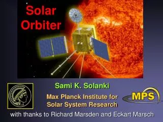
Solar Orbiter Remote Sensing Payload Working Group. Kick-off Meeting - ESTEC, May 16/17 2002. Solar Orbiter Remote Sensing Payload Working Group. Co-Chairs: Richard Harrison & Bernhard Fleck Bush, R. Stanford Univ. US VIM/helioeismology/ops

E N D
Solar Orbiter Remote Sensing Payload Working Group Kick-off Meeting - ESTEC, May 16/17 2002
Solar Orbiter Remote Sensing Payload Working Group Co-Chairs: Richard Harrison & Bernhard Fleck Bush, R. Stanford Univ. US VIM/helioeismology/ops Defise, M. CSL Liege B EUI/filters/thermal tests Fineschi, S. Univ. Torino I UVC/EUS/EUI Gabriel, A. IAS Orsay F EUI/EUS Gandorfer, A. ETH Zurich CH VIM/radiation damage Harra, L.K. MSSL UK EUS Harrison, R.A. RAL UK Co-Chair / EUS Hassler, D.M. SWRi Boulder US EUS Hochedez, J.-F. ORB Brussels B EUI/data processing/detectors Korendyke, C. NRL US UVC/EUS Lamy, P. Marseille F UVC Lin, R. Univ. Berkeley US Gamma-ray, hard X-ray Martinez-Pillet IAC Tenerife ES VIM Poletto, L. Univ. Padoa I EUS/optics Schuehle, U. MPAe D EUS/EUI Sigwarth, M. KIS Freiburg D VIM ESA Science Payloads Technology Division: T. Appourchaux
Solar Orbiter Remote Sensing Payload Working Group • Task of the Working Group • [From Call for Letters of Interest 1/11/01] • Arrive at a full definition of the instruments needed to achieve the primary scientific goals of the mission, including spacecraft interfaces; • Address the potential problem areas arising as a result of the extreme thermal and radiation environment that will be encountered, and to identify necessary technological developments.
Solar Orbiter Remote Sensing Payload Working Group • Task of the Working Group[continued] • Note 1: Task is not to provide complete designs, but to demonstrate feasibility. We must be happy that the instrument package can function given the mission environment, and the spacecraft and operational constraints. • Note 2: We must identify problem areas/challenges and ensure that they can be solved/addressed. • Product of Study • 1. Study Report to ESA • 2. Recommendations for tests/investigations/strategy etc… • 3. Anything we feel is appropriate?
Solar Orbiter Remote Sensing Payload Working Group • Task of the Working Group[continued] • We have a wonderful opportunity to develop and enhance the S.O. mission, to raise its profile – and to oversee studies to demonstrate the feasibility of the mission - i.e. to make it happen! • Caution: By nature we are homing in on the problem areas of the mission – in great detail. It would be easy to be negative – these are challenges not problems!
Solar Orbiter Remote Sensing Payload Working Group • Order of Play • Establish a complete list of instruments to consider (include additions if appropriate) • Establish a complete list of challenges/problems/concerns - For each instrument in turn - For the mission (‘global’ issues) • Define activities required to progress (minor or major studies, test activities, collaborative studies with BepiColombo...)
Solar Orbiter Remote Sensing Payload Working Group • Strawman Instrumentation • VIM: Visible Light Imager and Magnetograph Vector magnetograph; local area helioseismology • EUS: Extreme-UV Spectrometer Plasma diagnostic spectrometer/imager • EUI: EUV Imager EUV coronal imager • UVC: UV and Visible Light Coronagraph Visible, H I and He II coronagraph • RAD: Radiometer Four channel radiometer
Solar Orbiter Remote Sensing Payload Working Group • Other Remote Sensing Instrumentation? • Higher energy imager - X-ray/gamma-ray? • Heliospheric Imager? [Both mentioned in the proposal] • Others?
Solar Orbiter Remote Sensing Payload Working Group Generic First-Cut list of problems/challenges Environmental Issues 1. Thermal loads (high and variable!) 2. Cosmic rays 3. Solar particle environment Mission/spacecraft Issues 1. Telemetry 2. Power 3. Mass 4. Autonomy 5. Pointing 6. On-board memory 7. Image Stabilisation 8. On-board intelligent operation 9. Size/Accommodation (instruments/radiators) 10. Sequences for evasive action 11. Methods for operations planning
Solar Orbiter Remote Sensing Payload Working Group Spacecraft Resources (in proposal) VIM 26 kg 25 W 20 kbit/s 30cm x40cm x120cm EUS 22 kg 25 W 17 kbit/s 30cm x15cm x 140cm EUI 36 kg 20 W 20 kbit/s 40cm x40cm x250cm UVC 17 kg 25 W 5 kbit/s 20cm x20cm x50cm RAD 4 kg 6.5 W 0.5 kbit/s 11cm x 11cm x 22cm
VIM Basic design: 25 cm Gregorian reflecting high-resolution telescope (HRT) & 5 cm full disc telescope (FDT) & filtergraph optics. Common telescope focal plane - i.e. 1 detector. 1. Thermal: Heat load (HRT) is 105 to 1679 W. From Proposal: - Primary SiC mirror passively cooled ‘to dispose of ~ 170 W’ which is absorbed by mirror. SiC ‘better static and dynamic thermal stability than other materials’. - ‘Gregorian design permits rejection of 96% of incident radiation at primary focus with a field stop - inclined mirror rejecting light out of spacecraft’. ‘Field stop also absorbs 170 W which requires passive cooling’. (i.e. 1679 W incident. 170 W radiated from primary. 96% of remaining 1509 W rejected at field stop, i.e. 1449 W, 60 W left. 170 W absorbed at field stop?! Need to see the numbers/calculations.) Questions: How many radiators? (primary, field stop, secondary?, detector?) What sizes? Has the full range of the heat load & its variability been considered fully? Need to accommodate rejection path.
VIM 2. Folding Mirror - Single point failure? A folding mirror is inserted into the HRT optical path to view the FDT image. Questions: VIM operation depends critically on this one mechanism operating effectively under extreme conditions? What is the impact of a failure of the mechanism and how can we avoid this? 3. CCD Cameras 2kx2k 10 micron pixel CCD detector baselined - ‘already common on the market today’. Question: Can camera survive particle environment? See notes on detectors.
VIM 4. Telemetry 2kx2k array. 20 kbit/s allocation. For 12 bits per pixel, best cadence is 42 min for full data return. Need better than order of magnitude improvement on this - even to values well under 1 min (must do significantly better than MDI). Some basic comments on compression, pixel summing and selection were made in proposal. Questions: To demonstrate truly that the VIM can function with such a telemetry allocation, a full study is required. We must not fly an instrument whose basic operation is compromised by the telemetry. 5. Mass A mass of 26 kg is estimated - in some detail. Question: How realistic is the mass estimate? On first glance I cannot see all of the mechanisms included (zoom, folding mirror mechanism…); does it include all electronics (the 2.7 kg appears to be for the CCD camera plus its electronics, what about mechanism control electronics, power supply, data handling electronics...); does it include the radiator(s), entire structure, baffles, door(?) etc…? See notes on mass.
VIM 6. FOV HRT: 0.28 arcsec pixels. 2048 x2048 array i.e. 573 arcsec (9.6 arcmin) FOV scale. Equal to 80,000 km at 0.2 AU. Can point to anywhere on Sun by tilting and decentering secondary mirror. Question: At 0.2 AU does this degrade optical performance significantly for limb observations? 7. Power 5 W for the CCD, 5 W for the image stabilisation, 10 W for the Fabry-Perot and oven, 5 W for the 2 polarisation modulation packages. Question: Is this realistic? What about the power consumption of the zoom, folding mirror and secondary mirror mechanisms? Does the CCD 5 W cover all electronics? 8. Other Questions - The optics box size is given. What about an electronics box? (size, mass?) - On board memory? (Each image is 48 Mbits.)
EUS Basic Design: 120 mm Ritchy-Chretian telescope feeding a spectrometer with variable line spacing grating and a 4kx4k APS detector system. 1. Thermal Primary receives 310.6 W at 0.2 AU. SiC, gold-coated primary, running hot, with dedicated radiator was adopted. Large radiators needed for primary, secondary and detector. New approach calls for off-axis version with heat-stop before secondary. Primary is highly reflecting, as is heat-stop. Smaller radiator for primary and manageable heat-load beyond stop. Question: Is this thermally viable? Need complete thermal model. How many radiators of what size? How does it cope with variable thermal load? A grazing-incidence design is also under consideration; the thermal aspects of this option should be studied as well.
EUS 2. Detector/Instrument Size To bring instrument to acceptable length, with required resolution, need small pixels. 4kx4k 9 micron APS array baselined in proposal. Instrument was 2.3 m long. New 5 micron pixel version is 1.5 m long. Question: Need to demonstrate that optical design can be refined to cater for 5 micron pixels. How will the instrument be visibly blind (intensifier or filter - where?)? See note on detectors for other issues. 3. Optical Design Rastering is performed by the secondary in the proposal design. In the more recent design, either the primary does the rastering or the instrument pointing is adjusted (to avoid the secondary seeing more than a ‘slit’. Question: Demonstrate that the primary can provide suitable optical performance to do this. Can we real;ly be happy that an option for continued instrument re-pointing to build up images is acceptable?
EUS 4. Pointing Mechanism This instrument will not have a capability to see the full Sun at 0.2 AU; this is driven by resolution requirements. However, the EUS concept requires an ability to choose targets. A re-pointing capability to select target areas on the Sun is required. Question: Is it necessary for this instrument to point independently? 5. Multilayers Multilayered optical surfaces are being considered to enhance the reflection at the target wavelength ranges (e.g. silicon/platinum). Question: Multilayering of the primary (as well as other surfaces) is under consideration, but concerns exist about the thermal effects (e.g. layer diffusion). The EUS primary was at 70 degrees. Can we demonstrate the integrity of the multilayers to extended periods of high temperature, say, 100 degrees? Is this of concern for EUI as well?
EUS 6. Telemetry Proposal allocation 17 kb/s. 4kx4k array, 12 bits (?) = 1.92 x 108 bits PER EXPOSURE (a rastered image is made up on many exposures). With the given telemetry, 167 min to return one exposure – i.e. tens of hours for a rastered image!! Proposal suggests selection and compression (much as with CDS & SUMER on SOHO) – However, selection of 25 lines (25 pix across each) with 10x (?) compression gives 3 min per exposure and tens of min per rastered image. Question: This instrument has a big telemetry problem, which needs a thorough study – Can we demonstrate that it can achieve the scientific requirements with such a telemetry allocation? 7. Stability Needs image stabilisation – unless spacecraft jitter variations timescale greater than exposure time. Question: Can we confirm the need for an image stabilisation capability now?
EUS 8. Mass Proposal mass breakdown did not include image stabilisation system. Other than that, policy of carbon fibre structure/APS/reduced size may achieve target. However, need more accurate estimate. Question: Can we produce a more accurate mass breakdown? 9. Length EUS was over 2 m long in the proposal. Probably too long for accommodation and mass. Current design under 1.5 m. Question: Can we refine the design concept to confirm the shorter length? 10. Protons and Coatings There was concern for CDS/SOHO about (hydrogen) bubbles forming under the mirror gold coating due to the impact of protons. This was tested and found to not be of concern for the flux at 1 AU. Question: Is this a potential problem at 0.2 AU? For more than EUS?
EUI Basic design: Cluster of imagers including a High Resolution Imager (HRI) (3 EUV off-axis Gregorian, 20 mm instruments) and Full Sun Imager (FSI) (1 EUV off-axis Gregorian, 20 mm instrument) 1. Length Proposal length was 2.5 m – driven mainly by baffle tubes. Question: Is this too long to accommodate on spacecraft? 2. Stability Pixel size is 0.25 arcsec. This requires an image stabilisation system. Proposal states ‘possibly making use of the VIM limb sensor to drive adjustments to the secondary.’ Question: This instrument needs image stabilisation. Is the VIM sensor option workable, or is there a better option?
EUI 3. Telemetry Then instrument has 4 2kx2k detectors. For the given telemetry rate of 20 kbit/s this gives a cadence of about 3 hours for a mode which returns all bands in turn (assuming 12 bit/pixel and no compression). Question: The telemetry and cadence issue must be addressed to bring cadences down to values of order minutes or, preferably, well under 1 minute? 4. Mass Proposal mass is 36 kg, for the 4 telescope assembly, plus pointing system, electronics, structure, detectors. Question: The mass of the image stabilisation system is not included; the detector mass is much lower than that for EUS for a similar system; the optics mass is very low; the harness is very light. What about radiator(s), and door? Can we demonstrate that the mass estimate is realistic? The current proposal design uses 9 micron pixels; can we reduce the whole instrument with 5 micron pixels?
EUI 5. Pointing It is argued that EUI needs an independent pointing system. Question: See separate note on pointing. 6. Thermal There is no thermal discussion in the proposal for EUI except for the discussion of the need for a long baffle system. This does cut out much of the solar disc, but a proper analysis is required. Question: Can we show that the EUI will cope with the thermal situation, with a thermal analysis and test activities? If we use 5 micron pixels and reduce the instrument size, will this help? 7. Multilayers The mirrors use multilayers, to tune to the different wavelengths. Question: As with EUS, can we demonstrate that multilayers will cope with the extreme thermal situation? A test activity may be required.
UVC Basic design: Externally occulted off-axis Gregorian telescope with multilayer mirrors and filters to obtain vsible, H I and He II bandpasses. 1. Pointing This is the one instrument with a continuous field of view centred on Sun centre. No pointing system was planned in the proposal. Question: Should we define the UVC boresight as the spacecraft boresight? How do we cater for the scenario where the spacecraft is used to point the other instruments to target areas? 2. Multilayers The mirrors use multilayers, to tune to the different wavelengths. Question: As with EUS and EUI, can we demonstrate that multilayers will cope with the extreme thermal situation? A test activity may be required.
UVC 3. Thermal The critical thermal question concerns the occulter heat-load and heat dissipation. This is recognised in the proposal and some estimates given. However, there is no quantitative discussion of the thermal effects in the rest of the instrument. In the proposal, the UVC is the only device for which some consideration is made of the variable heat input. Question: A more complete thermal model is required for the UVC. 4. Detectors UVC uses two detectors (UV and visible), 15 micron 4kx4k - baselined as one APS and one CID detector. Question: In common with the other instruments (EUS, EUI) we must ensure that the formats suggested are likely to be available and are sensible options. See detector notes.
UVC 5. Telemetry Estimated data volume of 260 Gbits per orbit suggesting a factor of 20 above the nominal telemetry rate of 5 kbit/s. This cannot be catered for with lossless compression. Question: Although the situation is not as extreme as for the other instruments (VIM, EUI, EUS), a proper analysis of the telemetry situation is required. 6. Mass The instrument mass is given as 17 kg for an 80 cm long instrument. Question: The mass breakdown is fair but does not seem to include theh harness, radiator(s), door(?). Can we make a thorough assessment of the mass? 7. Light Rejection UVC needs a light rejection path to space. Question: Can we accommodate this?
RAD Basic design: Room temperature four channel radiometer with electrically calibrated cavity receivers. 1. Telemetry The allocation is 500 bit/s. Question: Although RAD is not telemetry ‘thirsty’, 500 bit/s is a low rate. Is it sufficient? The proposal does not give any indication of this. Also, the proposal calls for 3.5 kbit/s during ‘check-out intervals’. How is this done? 2. Mass/Size The mass is given as 4 kg, for an instrument 11 cm x 11 cm x 22 cm. However, radiation shields extend this to 14 cm x 14 cm x 26 cm. Question: Does the mass estimate include radiation shields and larger size?
Solar Orbiter Remote Sensing Payload Working Group Mission-Specific Issues - 1. Environmental Issues 1. Thermal Loads 149 day cycle = 2,142 to 34,275 W/m2 (0.8 to 0.2 AU). Need to address thermal balance for high load values and for variation of thermal input. We must validate the designs through extensive modelling and tests. What facilities can be used for such testing? Alan Gabriel expresses great concern about the primary mirror temperatures - for VIM, EUS and EUI (in order). The feasibility of operating such systems must be addressed urgently. 2. Particle Environment Need to consider exposure to solar wind at 0.2 AU, flare/CME particles, cosmic rays - including a consideration of neutrons at 0.2 AU. This is an issue for detectors (see later slides) and even for optical coatings (see EUS slides).
Solar Orbiter Remote Sensing Payload Working Group Mission-Specific Issues - 2. Detectors CCD vs APS vs Diamond? (VIM, EUS, EUI, UVC) 1. Small pixels = small instruments. CCDs limited (~10 micron pixel about best can achieve). APS under ‘on order’ at 5 micron level (3kx4k Marconi/RAL). Diamond? 2. Array sizes: Up to 4kx4k arrays under discussion. OK for CCD and APS. What array sizes have been built for Diamond? 3. Mass: Need to save mass. For APS, individual pixel amplification and charge extraction. Needs less electronics = lower mass.
Solar Orbiter Remote Sensing Payload Working Group Detectors (continued) 4. Intensity: Bright events show significant blooming in SOHO instruments (EIT, CDS, LASCO) - for flares, bright-points, planets etc… This will be worse for Orbiter. Must have greater well-depth CCDs or use APS. 5a. Particle Environment: Cosmic Rays Non-solar cosmic rays should be about the same as for SOHO.
Solar Orbiter Remote Sensing Payload Working Group Detectors (continued) 5b. Particle Environment: Solar Wind Projecting naively from 1 AU values (~10 p/m3) we might expect 250 p/m3 in ‘normal’ conditions at 0.2 AU, with v ~ 400 km/s. Thus, we expect 106 hits/cm2.s (25x SOHO flux). Is this a worry? Perhaps not so much if the detectors are ‘buried’ (don’t view space directly) and if the protons are low enough energy (will be plenty of 100 keV protons, for example). Note: 109 direct proton hits ‘will kill a CCD’ - not so an APS… Note: what about neutrons? We might expect to see some. 15 min half life means that we may expect them - possibly only from flares but more often than for 1 AU. Concern over their cross section at the silicon lattice relative to protons. Needs investigation.
Solar Orbiter Remote Sensing Payload Working Group Detectors (continued) 5c. Particle Environment: Flares and shock (CME) particles Difficult to predict. Could argue that the chance of being hit by a flare proton(/neutron) ‘beam’ is the same as for, e.g. SOHO. What about from larger shocks? Would suggest that there is a greater chance of seeing energetic particles, but hard to calculate. Note: Hadrons can cause damage to the silicon lattice which causes traps that can ‘steal’ charge which can be transferred to other parts of the image. The APS minimises the problem by not transferring charge.
Solar Orbiter Remote Sensing Payload Working Group Mission-Specific Issues - 3. Mass Approaches: (i) Re-calculate ‘realistic’ mass from proposal, (ii) project the mass from previous instruments, (iii) Consider key ‘generic’ issues, (iv) ‘Centralise’ some activities: (iii) Generic: Small pixels = Small instrument (ii) Heritage: e.g. EUS CDS/SOHO (100 kg - aluminium structure - 1.7m length) EIS/Solar-B (60 kg - CF structure - 3 m length) EUS: target 22 kg, 1.4 m length, CF structure, APS detectors less massive than CCD system, BUT possible image stabilisation system. Conclusion - Optimistic, perhaps 30 kg better target? (iv) Detectors from several instruments feeding a common camera system (e.g. STEREO); shared structure (e.g. STEREO SCIP); no independent pointing systems…)
Solar Orbiter Remote Sensing Payload Working Group Mission-Specific Issues - 4. Pointing EUS sees part Sun. Proposal caters for independent pointing system, through ‘external’ legs. Scientific goals require the selection of targets. VIM (HRT) sees part Sun and can point independently using internal (secondary) mirror. EUI sees full Sun in FSI but partial Sun in HRI. Proposal included independent pointing mechanism. Requires the selection of targets. UVC sees full 360 degree corona - no active pointing required. RAD sees full Sun.
Solar Orbiter Remote Sensing Payload Working Group Mission-Specific Issues - 4. Pointing - Do we demand common pointing (EUI, EUS, VIM) to save mass and to stress policy of common JOPs - i.e. spacecraft pointing? Would need to cater for UVC pointing. - If so, how and when do we select targets? How would we do this in any case (separate pointing systems)? - We must be happy that the scientific requirements of the different instruments can be satisfied by a common pointing policy.
Solar Orbiter Remote Sensing Payload Working Group Other Mission-Specific Issues 5. Telemetry Telemetry is extremely limited for a mission carrying imagers, spectrometers and in-situ instruments (total 62.5 kbit/s). Question: Can we improve the situation with a combination of increased ground station coverage, more on board memory and compression? 6. Autonomy Solar Orbiter will not be operated with day to day contact, as with SOHO. In effect, we are dealing with an encounter mission with very limited contact. Question: Can we demonstrate that the proposed spacecraft and instruments can operate in the autonomous fashion required for this mission?
Solar Orbiter Remote Sensing Payload Working Group Other Mission-Specific Issues 7. On-board memory Question: Can we maximise the on-board memory to enable more flexibility during the passes - what are the options? 8. On-board intelligent operation Question: How will targets be identified and how will the instruments point to them - prediction of pointing or intelligent operation on board?
Solar Orbiter Remote Sensing Payload Working Group Other Mission-Specific Issues 9. Size-Accommodation Question: Can we define the maximum instrument length? How many radiators are required and of what size - can we accommodate this? Can we accommodate the instrument sizes, and optical rejection ‘windows’? 10. Sequences for Evasive Action Question: Are there any occasions for which evasive action would be required at instrument level (e.g. ‘seeing a flare’; particle storm; spacecraft thruster firing…)?
Solar Orbiter Remote Sensing Payload Working Group Other Mission-Specific Issues 11. Methods for Operations Planning Suggestion: Use SOHO-like JOP approach. Planning done on 149 day cycles with basic plan in place weeks before the passes and only minor updates (pointing/target selection) just prior to the pass. Requires target selection maybe a week before the event at the best - or using on-board target identification. Question: We must perform a detailed study of the operations planning for this mission to ensure that it can achieve the scientific requirements advertised.
Solar Orbiter Remote Sensing Payload Working Group Other Mission-Specific Issues 12. Broadcast Data (Space Weather) It has been suggested that some Solar Orbiter data be transmitted continuously at a low telemetry rate for Space Weather forecast and monitoring purposes. Question: What are the options? What data should be included in this (any from the remote sensing side)? What allocation of telemetry, and is it a feasible option? A study is required.
Solar Orbiter Remote Sensing Payload Working Group • Other Options to Save Mass/Money • Shared studies with BepiColombo • Recommend the removal of one or more instruments • Centralise some items (share structures in some cases, common pointing, share camera system…) • Shared launch? • Other options?
Solar Orbiter Remote Sensing Payload Working Group • What now? • Divide team into sub-groups by instrument - sub-groups ensure list of challenges/problems is complete by end of June? • In parallel, set up subgroup to ensure list of ‘global’ mission/spacecraft issues is complete by end of June? • Divide complete list into (i) global issues (e.g. planning/operation, pointing), (ii) issues involving one or more instrument* (e.g. detectors and multilayers at 0.2 AU), (iii) instrument specific issues (e.g. thermal design, grating procurement). *No need for every instrument study subgroup to look into issues common to more than one instrument.
Solar Orbiter Remote Sensing Payload Working Group • What now? • Chairs to assess and assign studies - see below. • Instrument subgroups to assess the instrument-specific issues. Address minor studies quickly and establish studies/suggest tests for major issues. • Global issues and multi-instrument issues to be addressed by other subgroups. • Set up working Web site to store information and for communication as we compile results and begin drafts of reports. • Mid-term meeting - when?