Download
1 / 31
310 likes | 409 Vues
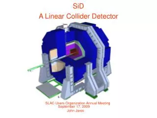
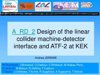
2. A_RD_2 Design of the linear collider machine-detector interface and ATF-2 at KEK. Ph.Bambade, J.Brossard, O.Dadoun, C.Rimbault, M.Alabau Pons, A.Jeremie, B.Bolzon, N.Geffroy, F.Cadoux, T.Tauchi, J.Urakawa, T.Kume, R.Sugahara, A. Sugiyama, T.Sanuki. ATF2. ATF2 objectives:

E N D
2 A_RD_2 Design of the linear collider machine-detector interface and ATF-2 at KEK Ph.Bambade, J.Brossard, O.Dadoun, C.Rimbault, M.Alabau Pons, A.Jeremie, B.Bolzon, N.Geffroy, F.Cadoux, T.Tauchi, J.Urakawa, T.Kume, R.Sugahara, A.Sugiyama, T.Sanuki
ATF2 • ATF2 objectives: • 37nm vertical size and 2.8 mm horizontal size beam at focal point in a reproducible and stable manner => flat beam as in ILC(a.r.80 for ATF2 and 110 for ILC) • stable trajectory (D<2nm) and intra-train feedback like in future ILC ILC demonstrator! Planning: Installation: 2007-2008 Beam: October 2008
Mechanical stabilisation QD0: 400kg mover: 25kg T-plate: 10kg
Mechanical stabilisation • Two main topics: • Measurements with magnets and movers • Study FD support
Mechanical stabilisation • Measurements with magnets and movers 4 movers arrived from SLAC: need some modifications to fix and adjust to CLIC table Measure vibrations with mock weight and eventually a real ATF2 FD magnet (but only one!) Modify movers to adjust to beam height when FD support finalised Mock weight (lead bricks) has arrived at Annecy and has been placed on table ready for measurements Mover T-plate being done: machine-shop time reserved and material ordered
Mechanical stabilisation The movers will be modified to agree with beam height: here the first draft when using the CLIC table to reduce the height by 8cm 40.64 cm 27.05 cm 32.64 cm (40.64 - 8)
Mechanical stabilisation 2. Study FD support Study CLIC table performance at low frequency Need to be compatible with precise measurement of beam shape and size at IP Finalise FD performance requirements at ATF2 Asked for money to transport table, but a new support will be sent when study finished (in time for beam commissioning)
FD support Initial idea: use CERN CLIC stabilized table Isolator Honeycomb support structure User Interface Controller :to provide communications with and diagnostics of the STACIS 2000 system Isolator: Stiff rubber: Passive damping One vertical geophone/actuator pair Two horizontal geophone/actuator pairs Active damping This table has been used with success to stabilize at nm level in the 1-50Hz rangeby CERN team! But ATF2 FD needs to be stable in the 0.1-30Hz.
2. Vibrations of the passive table Vertical direction: Integrated RMS ~Same response Damping Amplification Amplification 27 0.5 30 • Below 0.5Hz: No amplification or damping on the table • Above 0.5Hz: Amplification and damping begins only above ~30Hz
3. Vibrations of the active table Vertical direction: integrated RMS • Below 0.8Hz: Amplification on the table • Above 0.8Hz: Damping on the table Factor 7 of damping above 1.5Hz
Proposal1 :Rigid mount on floorMount both interferometer and magnet rigidly on floor without any stabilizer • Advantage • Tolerant for slow (coherent: ~0.1Hz?) floor motion • Simple & low cost Confirm rigidity of interferometer body Estimate effects of magnet originated vibration Interferometer • Disadvantage • Affected by high-speed (incoherent:1Hz~?) floor motion • Affected by distortion of Interferometer body and mounts • Affected by magnet (including cooling water, etc.) vibration Final magnet (mount table) Interference fringes Electron beam Confirm rigidity of mount Proposal Rigid mount Rigid mount Floor
Support structure and rigid fixing Less amplification factor at lower frequencies for concrete polymer Bolting Polymer concrete <Vertical direction>
Vibrations transmissibility study between table and floor • Magnitude of table transfer function measured at LAPP: amplification • Up to 20Hz: Table transfer function magnitude around 1 No big amplification or damping done by the table • Above 20Hz: Increase of table transfer function magnitude Ground motion amplification done by the table up to a factor 11 at 68Hz
Compare measurements to simulations • Simple block simulation done by Nicolas Geffroy: Full block with the table dimensions (240*90*60cm) Calculation of the density to obtain the table weight (700kg) Young modulus chosen (rigidity) to obtain the first eigenfrequency of the table in free-free configuration (230Hz) • First eigenfrequency at 56.2Hz: Well lower than in free-free configuration!!! • In agreement with transfer function measurements
What would happen if we use the block in ATF2? Relative motion between table and floor at ATF Ring Data from ATF floor • Integrated relative motion between floor and table at ATF Ring using table transfer function: - Above 0.1Hz: 5.95nm Below ATF tolerances (6nm)!!! - Above 50Hz: 0.78nm Negligible
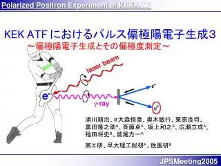
Interference fringes as a reference Scanning electron beam Electron beam to be measured Schematics of Shintake MonitorMeasure beam size using phase (=position and period) of interference fringe as a reference g-ray modulated by interference fringes
Analysis results for deformation mode of interferometer (1st ~5th) Large motion <-->Small motion 1st (42.4 Hz, Twist) 2nd (53.7 Hz, Bend) 3rd (73.7 Hz, Twist) Hit by impulse hammer and measure response by Acc. Sensor (Herz co. ltd. ) 4th (91.9 Hz, Twist) 5th (98.1 Hz, Twist)
Optimization of IR design Pair background with almost no Pt Inside diameter of TPC and FCAL influence on background => influence on the backscatter from beam calorimeter (BCAL) of Extraction hole =>pair background from the solenoid magnetic field
plain solenoid solenoid with anti-DID Optimization of solenoid magnetic field Anti-DID insert measurement equipment combining two Dipoles. The charged particle of low energy is led to Extraction hole. high high Low Low e- e+ e- e+
Optimization of the inside diameter of FCAL Avoid gammas in FCAL which come from BCAL Initial value of the aperture was optimized by calculation=> verification with simulation. FCAL CH2Mask BCAL Support Tube FCAL Inner Radius
Collider motivations for small crossing-angle ILC IR Orsay+Saclay workshop on design challenges of the small crossing-angle IR: 19-20 October 2006 http://ilcagenda.cern.ch/conferenceDisplay.py?confId=1150 http://ilcagenda.cern.ch/conferenceDisplay.py?confId=1149 very small 0 – 2 mrad large 14 – 25 mrad • shared magnets • coupled design • separate channels injection & extraction challenges & remedies approaches & risks • large L loss : x z • crab-crossing (R&D) • non-axial in solenoid • DID / anti-DID & • post / pre-IP bumps • post-IP losses • careful optics & • collimation • large magnet bores • electr. separators • preserve pre-IP beam • reflected background • emphasize post-IP beam • adds pre-IP constraints
Beam instrumentation first exchange of students and young scientists which should be encouraged at both sides
Travelling financed by AIL France-Japan • Meeting in Annecy: 20 participants from France, Japan, CERN, USA, UK and Spain http://ilcagenda.cern.ch/conferenceDisplay.py?confId=1176 • 3rd ATF2 ATF2 Project Meeting in KEK • Student trip to KEK for instrumentation work • This Workshop
Bid for 2007-2008 A_RD_2 :Collaboration on the ATF2 project at KEK and on the ILC Machine Detector Interface Members (same institutes as for 2006): Ph.Bambade, J.Brossard, O.Dadoun, C.Rimbault, M.Alabau Pons, Y.Régnier (LAL/France) A.Jeremie, F.Cadoux, N.Geffroy, B.Bolzon (LAPP/France) T.Tauchi, J.Urakawa, R.Sugahara, S.Kuroda, T.Okugi, T.Kume(KEK/Japan) A.Sugiyama (Saga University/Japan) T.Sanoki (Tokyo University/Japan) M.Verdéri, H.Guler => new participant from LLR/France
Bid for 2007-2008 A_RD_2 :Collaboration on the ATF2 project at KEK and on the ILC Machine Detector Interface The present proposal is a re-application to continue and expand our existing collaboration within the ATF2 project.
Bid for 2007-2008 A_RD_2 :Collaboration on the ATF2 project at KEK and on the ILC Machine Detector Interface
Conclusion • Very fruitful work: • Share experience with accelerators • Share expertise in signal analysis and vibration data and design of FD support is advancing well • Regular phone or video meetings • Travel to meet and work during workshops and ATF2 project meetings