Download
1 / 38
380 likes | 459 Vues
Machine Detector Interface Issues. Philip Burrows John Adams Institute Oxford University Thanks to: Tom Markiewicz. Outline. ‘Interaction hall’ considerations: push-pull configuration surface assembly ‘Beamline’ considerations: FF magnet package door opening/access

E N D
Machine Detector Interface Issues Philip Burrows John Adams Institute Oxford University Thanks to: Tom Markiewicz Philip Burrows SiD Meeting, Paris 11/02/08
Outline • ‘Interaction hall’ considerations: • push-pull configuration • surface assembly • ‘Beamline’ considerations: • FF magnet package • door opening/access • support of ‘R20’ module • beampipe engineering • Outlook Philip Burrows SiD Meeting, Paris 11/02/08
Push-pull: SiD assumptions • Having two detectors on beamline ‘permanently’, and sharing the luminosity, i.e. two IPs, is clearly the ideal solution for physics • Luminosity delivery to two IPs, with fast switchover between IPs, is not possible • Two detectors in push-pull mode will: • - save cost of one BDS • - increase likelihood of two detectors from start • - provide equal access to luminosity for both detectors Philip Burrows SiD Meeting, Paris 11/02/08
SiD statement on technical Issues • Push-pull can probably be engineered to work • - many technical issues will need to be solved • Full access to offline detector is mandatory • Best accomplished with self-shielding detectors • - self shielding is technically feasible • Mechanisms for moving detector should not reduce acceptance • Need to align ‘captured’ beamline components independent of overall detector position Philip Burrows SiD Meeting, Paris 11/02/08
SiD: technical questions • Can detector be engineered so magnetic field map remains invariant under detector in/out? • Can tracking chamber alignment be restored without calibration runs (eg. with internal alignment system)? • Can detector remain fully operable in ‘out’ position? • - cosmic ray data-taking to maintain operability • Can switchover time be made short enough? Philip Burrows SiD Meeting, Paris 11/02/08
SiD: sociological issues • Need well defined procedure for scheduling swaps • Machine luminosity must be shared equitably • Period between swaps should be of order 1 month: - neither detector can gain significant lumi advantage in 1 period • Switch-over time << running period Philip Burrows SiD Meeting, Paris 11/02/08
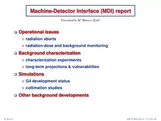
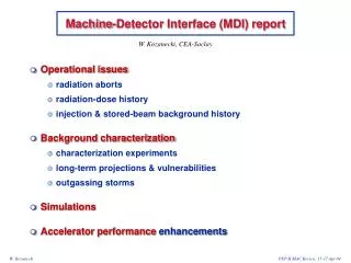
Concept which does not rely on self-shielding detector Platform for electronic and services (~10*8*8m). Shielded (~0.5m of concrete) from five sides. Moves with detector. Also provide vibration isolation. accessible during run (radiation worker) fence not accessible during run accessible during run (general personnel) Seryi Philip Burrows SiD Meeting, Paris 11/02/08
On-surface (a la CMS) detector assembly • According to tentative CF&S schedule, detector hall would not be ready for detector assembly until 4y11m after project start • If so, cannot fit into the goal of “7 years until first beam” and “8 years until physics run” • Surface assembly allows earlier start by 2-2.5 years and meets this goal • The collider hall size is also smaller in this case • - surface building needed, but potential savings still substantial • Assumptions were made on sizes of underground hall + surface building, shafts, cranes above and below ground … will be revisited • - needs serious engineering study of assembly, installation, access, safety, services, cabling … Philip Burrows SiD Meeting, Paris 11/02/08
CMS assembly approach: • Assembled on the surface in parallel with underground work • Allows pre-commissioning before lowering • Lowering using dedicated heavy lifting equipment: • 15 loads, 300-> 2000t • Potential for big time saving • Reduce size of underground hall required Philip Burrows SiD Meeting, Paris 11/02/08
Air-pads at CMS Single air-pad capacity ~385tons (for the first end-cap disk which weighs 1400 tons). Each of air-pads equipped with hydraulic jack for fine adjustment in height, also allowing exchange of air pad if needed. Lift is ~8mm for 385t units. Cracks in the floor should be avoided, to prevent damage of the floor by compressed air (up to 50bars) – use steel plates (4cm thick). [Alain Herve, et al.] SiD also exploring ‘Hillman rollers’ Photo from the talk by Y.Sugimoto, http://ilcphys.kek.jp/meeting/lcdds/archives/2006-10-03/ Seryi Philip Burrows SiD Meeting, Paris 11/02/08
SiD surface assembly considerations (Marty) Solid Edge Model Philip Burrows SiD Meeting, Paris 11/02/08
Sequence of Operations • Detector subassembly construction & surface tests • Octants of muon chamber instrumented barrel yoke, barrel Hcal, barrel Ecal • Four sub-modules of EC return flux instrumented with muon chambers, donut Hcal, Ecal • Tracker, vertex and FCAL packages • Surface Magnet test • Assemble barrel support and the bottom 5/8 flux return octants • Drop in coil & cover with remaining 3/8 octants • Assemble two door legs and 4 360° (180 °?) plates of flux return • Test magnet and disassemble • Lower detector chunks • Reassemble lower barrel iron with supports below ground • Load barrel HCAL and ECAL modules into coil cryostat via threaded beam • Lower loaded coil package and capture with upper barrel yoke segments • Depending on crane capacity • Lower fully assembled door • Lower door pieces, the last plate with the Endcap Ecal & Hcal, and reassemble • Tracker, VXD and FCAL installed below ground at end • ‘Surface assembly seems ok, but will require careful planning’ Philip Burrows SiD Meeting, Paris 11/02/08
Surface assembly parameters (Marty) Philip Burrows SiD Meeting, Paris 11/02/08
Surface assembly parameters (Marty) Philip Burrows SiD Meeting, Paris 11/02/08
Surface assembly parameters (Marty) Philip Burrows SiD Meeting, Paris 11/02/08
Surface assembly parameters (Marty) Philip Burrows SiD Meeting, Paris 11/02/08
Surface assembly parameters (Marty) Philip Burrows SiD Meeting, Paris 11/02/08
Surface assembly parameters (Marty) Philip Burrows SiD Meeting, Paris 11/02/08
BDS IR-related CF&S master table Philip Burrows SiD Meeting, Paris 11/02/08
Beampipe SiD inner IR layout 70mm x 1.7m AntiSolenoid Cryostat Space to Open Door 60cm OD Support Tube 512 mm OD Cryostat 305 mm OD Cryostat 38cm OD Support Tube Philip Burrows SiD Meeting, Paris 11/02/08
Force neutral anti-solenoid: (Parker) Philip Burrows SiD Meeting, Paris 11/02/08
QD0 + QDEX1A + Anti-Solenoid in Cryostat Philip Burrows SiD Meeting, Paris 11/02/08
Plan View - Details Philip Burrows SiD Meeting, Paris 11/02/08
Elevation View - Details Philip Burrows SiD Meeting, Paris 11/02/08
QD0 Cryostat in SiD @ L*=3.664m 264mm 370mm 3258mm 380mm 524mm Feedback BPM 763mm Beamcal Rear @ 3.300m Philip Burrows SiD Meeting, Paris 11/02/08
smaller detector QF1 warm QD0 smaller L* vacuum connection & feedback kicker common cryostat larger detector larger L* Seryi Philip Burrows SiD Meeting, Paris 11/02/08
Seryi Proposal: Fix QF1 @ 9.6m, L* chosen by Detector Concept: Study Collimation & Optics Sensitivity Philip Burrows SiD Meeting, Paris 11/02/08
SiD r<50cm, L*=3.664 Door Closed Liquid He Line 30mm 25.6mm 2207mm 3339mm Philip Burrows SiD Meeting, Paris 11/02/08
SiD r<50cm, L*=3.664 Door Open Liquid He Line Philip Burrows SiD Meeting, Paris 11/02/08
Door Closed, Permanent QD0 Liquid He Line Liquid He Line “PACMAN” ShieldingCLOSED Door Earthquake “Foot” Philip Burrows SiD Meeting, Paris 11/02/08
Door Open, Permanent QD0 Liquid He Line Liquid He Line “PACMAN” Shielding Philip Burrows SiD Meeting, Paris 11/02/08
FCAL/QD0 Supported with Door Closed QD0 FCAL Door Philip Burrows SiD Meeting, Paris 11/02/08
FCAL/QD0 Supported with Door Open QD0 FCAL Rail Extensions Door Philip Burrows SiD Meeting, Paris 11/02/08
Detail of beampipe (red) - ongoing Philip Burrows SiD Meeting, Paris 11/02/08
12mm Beam Pipe and VXD Detail Philip Burrows SiD Meeting, Paris 11/02/08
Three beampipe shapes have been considered over time for SiD • Flat at 12mm for VXD, flared to O.D. of Lumical (190mm) @ zmin = 1.68m of endcap ECAL • Flat at 12mm for VXD, flared to I.D. of Lumical (86.5mm) @ zmin = 1.68m of endcap ECAL • Flat at 12mm for VXD, flared rapidly to clear pair stay free until r=86.5mm (rmin of Lumical @ zmin = 1.68m), then cylindrical • In all cases, beam pipe then becomes conic and follows inner surface of mask until beampipe Philip Burrows SiD Meeting, Paris 11/02/08
Conceptual Solution for R20 Mechanics is Needed • Support points • Bellows • Flanges • Alignment and adjustment features • Vacuum features (if any) at z<7m (end of QD0 cryostat) • Cable & Gas service routing • Rethinking of access requirements in PUSH-PULL • On-beamline access for rapid repair • Off-beamline access for VXD or TRACKER replacement Philip Burrows SiD Meeting, Paris 11/02/08
Summary • GDE RDR BDS baseline comprises a conceptual model of • MDI based on push-pull + surface assembly • MDI complex area requiring careful design • Self-consistent conceptual scheme for SiD MDI has been developed • IR engineering workshop September 2007 • Engineering, engineering, engineering! • ‘macroscopic’: buildings, shafts, caverns, cranes … • ‘microscopic’: beampipes, valves, bellows, flanges … Philip Burrows SiD Meeting, Paris 11/02/08