Download
1 / 35
350 likes | 353 Vues
CLIC Machine-Detector Interface Working Group (MDI). Emmanuel Tsesmelis CERN TS/LEA CLIC-ACE of 3 September 2008. Mandate of MDI Working Group.

E N D
CLIC Machine-Detector Interface Working Group (MDI) Emmanuel Tsesmelis CERN TS/LEA CLIC-ACE of 3 September 2008
Mandate of MDI Working Group • The CLIC Machine Detector Interface (MDI) Working Group provides a forum where those technically responsible for issues at the interface between the machine and experiments can meet and discuss matters of mutual interest in preparation for the CLIC Conceptual Design Report. • The subjects treated cover technical items of common importance to the machine and experiments and include, but not limited to, the specification of the experimental areas, the experimental beampipes and vacuum, the estimation of the machine-induced background at the particle detectors, the radiation shielding and monitoring, the instrumentation in and around the particle detectors required to measure beam parameters, the data exchange and common safety issues. • The Working Group will also provide a forum to discuss issues of common interest for the machine and detector, such as the machine performance (luminosity and background measurement and monitoring) for the experiments. • The Working Group acts in close collaboration with other CLIC working groups (Civil Engineering & Services WG, Beam Dynamics & Beam Delivery WG, Physics & Detector WG, and the Stabilisation WG) and reports to the CLIC Technical Committee.
Organization • Membership • Co-Chairpersons : D. Schulte & E. Tsesmelis • Beam Delivery System design – R. Tomas Garcia • Machine-induced background – H. Burkhardt • Collimation system – F. Zimmermann • Luminosity performance simulations – J. Resta-Lopez • Design and integration of spent beam line – K. Elsener, V. Ziemann • Experimental beam pipe & vacuum – R. Veness • Representatives from relevant CTC WGs • Civil Engineering & Services WG - J. Osborne • Beam Dynamics & Beam Delivery WG - D. Schulte • Physics & Detector WG - A. Gaddi • Stabilisation WG – C. Hauviller • Regular meetings planned at a monthly frequency. • Work together with ILC in areas of synergy.
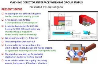
Interaction Region Lay-out • Distance L* between final quadrupole and IP is being evaluated • L* < 3.5. m. compromises luminosity • 3.5 < L* < 4.3 m. yields similar luminosity • Design of final focusing doublet is challenging • High gradient required. • Mechanical supports need to be very stable due to vibrational transmission from detectors. • A first design of a permanent magnet has been done (S. Russenschuck et al.) • Superconducting quadrupoles very challenging due to stability issues but would allow energy adjustments • Perhaps some hybrid approach should be studied.
Push-Pull Scenario • Baseline scenario assumes two particle detectors that share occupancy of the interaction point in push-pull mode. • Keep a two-beam delivery system under conceptual investigation while detailed engineering study of push-pull mode is on-going. • The two particle detectors and associated infrastructure/services should be arranged in such a way as to facilitate a rapid change-over. • Engineer the mechanical particle detector concept for push-pull capability. • Access to the inner components of the particle detector (e.g. vertex detector). • Maintenance of internal alignment of the particle detector and need to avoid recalibration after a move. • Ability to service the various superconducting elements of the particle detector during and after a move. • Design of underground experiment cavern should be such that one particle detector can be serviced while the other one is running.
Beam Delivery System • Elements of the BDS in close proximity to the particle detectors require careful engineering and integration. • Magnet systems (final focusing, corrector, kicker, extraction line), beam instrumentation, and crab cavities. • Connection of magnet cryostat(s) with the particle detector. • Support of the magnets while minimising the vibration transmission between the magnets and the particle detector. • Depends on type of magnets (permanent vs. pulsed).
Spectrometer Magnetic Fields • Main problem is coupling of the beams to the spectrometer solenoid field. • Due to crossing angle. • Yields statistical energy fluctuations. • Previous studies showed that 4 T are the acceptable limit for 20 mrad. • Currently including the detector solenoid field into the main beam tracking code PLACET. • End fringe fields are of particular importance. • The as-measured CMS solenoid magnetic field is being used.
Terms of Reference • Within the overall framework of strengthening the collaboration and synergy between CLIC and ILC, the Beam Delivery Systems and Machine Detector Interface Working Group provides a forum where those technically responsible for the beam delivery systems and for the issues at the interface between the machines and experiments from the ILC and CLIC projects can meet and discuss issues of mutual interest. • The subjects treated cover everything of common importance to the machines and experiments and includes, but not limited to, the machine performance for the experiments, the design and integration of the beam delivery system and the corresponding interaction regions and experimental areas, the experimental beampipes and vacuum, the radiation shielding and monitoring, the collimation system, the beam instrumentation, the luminosity and background measurement and monitoring, the mechanical supports and stabilisation, the design of the near-beam forward detectors, the data exchange and common safety issues. • The Working Group will endeavour to develop and use common standards and codes and undertake common studies. • The Working Group reports to both the CLIC and ILC Project Managements.
Topics of Common Interest • Experimental area lay-out and design. • Infrastructure/services, push-pull mode, crossing angle. • Experimental beam pipe and vacuum system. • Final focusing magnets. • Background and luminosity studies. • Common simulation tools. • Studies of machine-induced backgrounds and mitigation strategies. • Study of beam-beam background and luminosity spectrum. • Masking system. • Spectrometer magnet design and field. • Forward calorimetry. • Support, stabilisation and alignment of machine elements inside particle detector.
CLIC-ILC MDI Collaboration Alain Herve et al.
Summary and Conclusions • Machine-detector interface considerations/studies are central to CLIC. • An MDI WG has thus been set up to co-ordinate such studies. • Work on the MDI is on-going in the following areas: • Lay-out of the interaction region • Study of backgrounds • Luminosity spectrum • Integration of machine elements inside the particle detectors • Additional help in issues of the MDI is most welcome.