Download
1 / 28
540 likes | 985 Vues
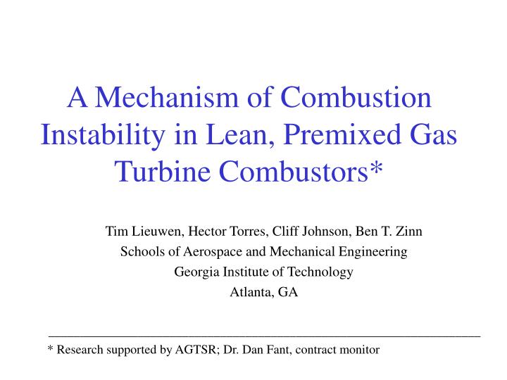
A Mechanism of Combustion Instability in Lean, Premixed Gas Turbine Combustors*. Tim Lieuwen, Hector Torres, Cliff Johnson, Ben T. Zinn Schools of Aerospace and Mechanical Engineering Georgia Institute of Technology Atlanta, GA

E N D
A Mechanism of Combustion Instability in Lean, Premixed Gas Turbine Combustors* Tim Lieuwen, Hector Torres, Cliff Johnson, Ben T. Zinn Schools of Aerospace and Mechanical Engineering Georgia Institute of Technology Atlanta, GA ____________________________________________________________________ * Research supported by AGTSR; Dr. Dan Fant, contract monitor
Combustion instabilities are an important problem hindering the development of LP industrial gas turbines Flame Flashback or blowoff - constrains regions of operability Fatigue Cracking of Liners - reduces combustor life Development of approaches to suppress these instabilities requires understanding the key physical processes responsible for their initiation. Combustion Instabilities in Lean Premixed (LP) Gas Turbines
Combustion Instabilities occur when: Energy Addition by Combustion Process (Rayleigh Criterion) Damping Mechanisms Radiation through boundaries Viscosity, heat conduction Occurrence of Combustion Instabilities Energy addition to the acoustic field by unsteady combustion process > Energy losses due to dissipation dE/dt ~ <p’q’>
Heat Release Oscillations AcousticOscillations Flow and Mixture Perturbations Mechanisms of Combustion Instability
Identifying the Mechanism Responsible for Instability Initiation • A number of processes are simultaneously present in combustors that cause heat release fluctuations: • Pulsations in fuel supply rate • Pressure and/or velocity dependent burning rate • Vortex shedding • Changes in flame area • Periodic changes in mixture composition
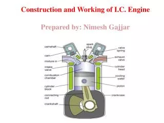
Flow and Reaction Processes in Gas Turbine Combustors Fuel Inflow Flame Stabilization Heat Losses Convection Swirling Mixing Flame and Flow Instabilities Air Inflow Chemical Reaction Exhausting
Combustion process becomes very sensitive to disturbances in composition under lean conditions Sensitivity of Lean Combustion Systems to Disturbances in Mixture Composition Characteristic Chemical time, s Zukoski's Experimental Data
Combustion process becomes very sensitive to disturbances in composition under lean conditions Sensitivity of Lean Combustion Systems to Disturbances in Mixture Composition 0.0015 0.001 Characteristic Chemical Time, s 0.0005 0 0.5 0.7 0.9 1.1 1.3 1.5 1.7 1.9 Equivalence Ratio Zukoski's Experimental Data
Recent combustor stability models that capture this mechanism: Lieuwen and Zinn, AIAA Paper # 98-0641, 27th Int’l Symposium on Combustion Peraccio and Proscia, ASME Paper # 98-GT-269 Heat Release Oscillations AcousticOscillationsin Inlet andFuel Lines Equivalence Ratio Fluctuations A Possible Mechanism for Combustion Instabilities
Time evolution of disturbances responsible for the onset of instability
Time evolution of disturbances responsible for the onset of instability (continued) • Combustion process adds energy to the acoustic field when: • (tci + tpv + tf +tconvect + teq)/T = 1, 2, 3, ... • Simplifications: • Typical geometries: tci/T~ 0 • Choked Fuel Injector tf/T=1/2 • teq essentially an additional convective time • discussed extensively in paper
Time evolution of disturbances responsible for the onset of instability (continued) • Combustion process adds energy to the acoustic field when: • (tpv + tconvect)/T = 1/2, 3/2, … • Implies that significant combustors parameters are : • Natural modes of combustor - T = 1/f • Inlet velocity - tconvect • Fuel injector location - tconvect • Upstream boundary condition of inlet - tpv • Length of inlet - tpv = Linj/u
Dependence of Instability Region on Combustor Configuration • Conclusion: For fixed geometry, instabilities can occur when tconvect/T = f*Linj/u constant • i.e., when uinlet=constant x f Penn State Facility - GT Facility - DOE Facility -
Combustor Section-Front View Fuel Hot Products Air
Effect of Inlet Velocity on Instability Amplitude and Frequency • In both cases, peak amplitude occurs where tconvect/T 1.1-1.2
Effect of Inlet Velocity on Instability Frequency uinlet=36 m/s uinlet=18 m/s uinlet=25 m/s
Inter-dependence of Instability Frequency and Inlet Velocity
Comparisons of Theory with Georgia Tech Data(Rigid Upstream Boundary) Conditions: u=10- 50 m/s f = 0.65-0.9 p=1-9 atm
Comparisons of Theory with Georgia Tech Data(Rigid Upstream Boundary) Theoretical Predictions Conditions: u=10- 50 m/s f = 0.65-0.9 p=1-9 atm
Comparisons of Theory with DOE Data(Pressure Release Upstream Boundary) Theoretical Predictions Conditions: u=30- 60 m/s f = 0.6-0.8 p=5-10 atm 3 Fuel injector locations
Comparisons of Theory with Penn State Data(Anechoic Upstream Boundary) Theoretical Predictions Conditions: Tin=600-740 K f = 0.4-0.7 p=2.5-7 atm 3 Fuel injector locations
Conclusions • Experimental observed stability limits consistent with theoretical predictions • Suggests that instabilities are initiated by a feedback loop between the combustion process, combustor acoustics, and fluctuations in reactants composition • Characteristic time analysis illustrates key processes in this mechanism and suggests methods for passive control
0.0001 s 0.001 s 0.01 s 0.1 s 1 s Characteristic Times Associated with Combustor Processes Acoustic Period 100 - 500 Hz Oscillations Chemical Kinetics Convection Heat Loss, Diffusion Mixing Swirling Flow Turnover Time
Convective Processes in Gas Turbine Combustors • Reactive mixture composition • Flame Dynamics - Response of flame to flow disturbances • Flow Instabilities - Distortion of flame by convecting vortex structure t~Linjector/u t~Lflame/u t~Lflame/u
Recent Measurements at U. Cal -BerkeleyR. Mongia, R. Dibble, J. Lovett, ASME Paper# 98-GT-304 Combustor Pressure Spectrum Methane Mole Fraction Spectrum
Unsteady WSR model subjected to perturbations in the inlet f. Response of the unsteady rate of reaction increased as much as 200 times as f was decreased from stoichiometric to lean mixtures Conclusion: f oscillations induce strong heat release oscillations that can drive combustion instabilities under lean conditions Results of a well-stirred reactor (WSR) model From Lieuwen, T., Neumeier, Y., Zinn, B.T., Comb. Sci. and Tech, Vol. 135, 1-6, 1998.
Phased Locked Images of Combustion Instability • Line of sight (top half of picture) and Abel inverted (bottom half of picture) images of CH Chemiluminescence of 200 Hz. instability Flow