Download
1 / 28
380 likes | 1.03k Vues
Asynchronous Counters. Lecture Overview. Classifications of Counters Definitions Asynchronous Counter… J – K Flip Flops D Flip Flops Up Counters Down Counters Truncated Counters Design Example. Classifications of Counters. Asynchronous Counters

E N D
Lecture Overview • Classifications of Counters • Definitions • Asynchronous Counter… • J – K Flip Flops • D Flip Flops • Up Counters • Down Counters • Truncated Counters • Design Example
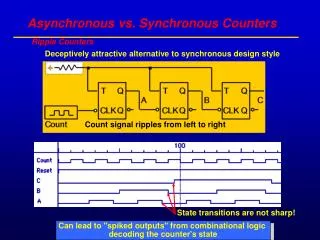
Classifications of Counters Asynchronous Counters • Only the first flip-flop is clocked by an external clock. All subsequent flip-flops are clocked by the output of the preceding flip-flop. • Asynchronous counters are slower than synchronous counters because of the delay in the transmission of the pulses from flip-flop to flip-flop. • Asynchronous counters are also called ripple-counters because of the way the clock pulse ripples it way through the flip-flops.
Classifications of Counters Synchronous Counters • All flip-flops are clocked simultaneously by an external clock. • Synchronous counters are faster than asynchronous counters because of the simultaneous clocking. • Synchronous counters are an example of state machine design because they have a set of states and a set of transition rules for moving between those states after each clocked event.
States / Modulus / Flip-Flops • The number of flip-flops determines the count limit or number of states. (STATES = 2 # of flip flops) • The number of states used is called the MODULUS. • For example, a Modulus-12 counter would count from 0 (0000) to 11 (1011) and requires four flip-flops (16 states - 12 used).
1 Bit Asynch-Counter / Modulus 2 With Timing Diagram from Logic Analyzer
2 Bit Asynch-Counter / Modulus 4 With Timing Diagram from Logic Analyzer 1 0 1 1 MSB 0 0 LSB 0 1 0 1 0 1 0 1 0 0 1 1 0 0
2 Bit Asynch-Counter / Modulus 4 With Timing Diagram from Logic Analyzer Tip for using the Logic Analyzer: Double click here to open the analyzer
Leave on internal Set this clock to be at least 10 times faster than the circuit clock. Click Here to open Clock setup
2 Bit Asynch-Counter / Modulus 4 With Timing Diagram from Logic Analyzer
Q0 Q1 Q2 The Ripple Effect…
Q0 Q1 Q2 3 4 2 0 Ripple Effect…The Problem
Six Examples • Modulus 4 Up Counter with Negative Edge Triggered Flip-Flops • Modulus 4 Down Counter with Negative Edge Triggered Flip-Flops • Modulus 4 Up Counter with Positive Edge Triggered Flip-Flops • Modulus 4 Down Counter with Positive Edge Triggered Flip-Flops • Truncated Counter • Counter Design
Asynchronous Counter Design Steps • Select Type • Up or Down • Modules • Select Flip-Flop Type • J-K or D • Positive Edge Trigger (PET) or Negative Edge Trigger (NET) • Determine Number of Flip-Flops • (2# Flip-Flop Modules)
Asynchronous Counter Design Steps • Design Basic Counters • Same polarity for down counters: • Opposite polarity for up counters: • Design Limits Logic • Input to logic is count that is one past the end of sequence.
Design Example • Select Type • Up or Down • Modules • Select Flip-Flop Type • J-K or D • Positive Edge Trigger (PET) or Negative Edge Trigger (NET) • Determine Number of Flip-Flops • (2# Flip-Flop Modules) MOD – 14 (0..13) 24 Flip-Flop 16
Design Example • Design Basic Counters • Same polarity for down counters: • Opposite polarity for up counters: • Design Limits Logic • Input to logic is count that is one past the end of sequence. Limit 13+1 = 14 (1110)