Download

1 / 23
230 likes | 244 Vues
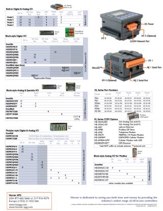
Training. Profibus/Feb99OG/RevFeb99OG/001. U ASI ASI ACTIVE. POWER. ADDRESS/ERROR. FX2N-32ASI-M. MODE SET. PRJ MODE PRG ENABLE FROM/TO CONFIG ERR. FX2N-32ASI-M / Specification. Item Description. Maximum Number of Max. 31 slave units

E N D
Training Profibus/Feb99OG/RevFeb99OG/001
U ASI ASI ACTIVE POWER ADDRESS/ERROR FX2N-32ASI-M MODE SET PRJ MODE PRG ENABLE FROM/TO CONFIG ERR FX2N-32ASI-M / Specification Item Description Maximum Number of Max. 31 slave units Controllable Units (up to 4 inputs and outputs per slave address) I/O Refresh Time Max. 5ms (connecting maximum I/O points) Communication Speed 167kbps Communication Method APM (Alternating Pulse Modulation) Network Type Bus network type (Free topology) Total Extension Distance Max 100 m ( ext. up 300 m with 2 repeaters) Number of Occupied 8 points taken from the programmable I/O Points controller bus (can be either input or output) Applicable Programmable FX2N Series, FX0N Series controller (Total system I/O points: 256 or less) Communication with FROM / TO instruction Programmable Controller Display (7 Segment) 2 column (slave address / error code)
Item Description Power Lit when 5V DC power supplied from main unit U ASI ASI ACTIVE U ASI Lit when external power supplied from the ASI Power supply ASI ACTIVE Lit when ASI system is in normal operation mode POWER ADDRESS/ERROR PRJ MODE Lit when 32ASI-M is in configuration mode PRJ ENABLE Lit when 32ASI-M is in automatic address programming enable FROM / TO Lit when 32ASI-M is accessed from main unit FX2N-32ASI-M CONFIG ERR Lit when ASI system has a configuration error MODE SET PRJ MODE PRG ENABLE FROM/TO CONFIG ERR Item Description MODE Used to switch between “Protected Operation Mode” and “Configuration Mode” SET Used to Set or delete the slaves address LED Indication / MODE,SET button
Master Start-Up - No data communication on the AS-Interface. If AS-Interface is not sufficiently powered “U ASI” LED is not lit, the master remains in off-line phase. <40> Offline Phase - The ASI remains in detection phase until it finds at least one slave or if two slave have double addressing. <41> Detection Phase - Activates the slave(s) which 32ASI-M found in the detection phase. This enables access to the AS-Interface slaves data connection. <42> Activation Phase - The 32ASI-M can exchange data with all active slaves. It transmits management messages and looks for and activates newly connected slaves. - Normal operation mode contains the “Protec- ted mode” and the Configuration Mode. <43> Start of Normal Operation < No display > Protected Oper. Mode < Detect. Slaves> Configuration Mode
U ASI ASI ACTIVE POWER ADDRESS/ERROR FX2N-32ASI-M MODE SET PRJ MODE PRG ENABLE FROM/TO CONFIG ERR Configuration MODE and Protected Operating Mode The Mode can be changed by: - operating the switch on the 32ASI-M - or by setting BFM #0 (bit 2,3) The switch on the 32-ASI can be disabled to prevent mis-operation - the mode can still be changed by a command from the PLC - the disabled switch can be operate when the 32ASI-M is in “Offline-Phase”
U ASI ASI ACTIVE POWER ADDRESS/ERROR FX2N-32ASI-M MODE SET PRJ MODE PRG ENABLE FROM/TO CONFIG ERR Configuration MODE and Protected Operating Mode Switching to “Configuration Mode” by MODE button - Press “MODE” button more than 5 seconds Switching to “Protected Operation Mode” by MODE button - Press “MODE” button less than 5 seconds - 32ASI-M exits the configuration mode without copying the configuration to setpoint configuration. - Press “MODE” button more than 5 seconds - 32ASI-M exits the configuration mode and copying the configuration to setpoint configuration. 32ASI-M stores this configuration into the List of Projected Slaves (LPS), and stores the actual parameter to permanent configuration.
U ASI ASI ACTIVE POWER ADDRESS/ERROR FX2N-32ASI-M MODE SET PRJ MODE PRG ENABLE FROM/TO CONFIG ERR Configuration MODE Set the slave address number: - The green “PRJ MODE LED” lights up - For active slave - all recognised slave are activated with exception of slave 0 - Displayed message - 32ASI-Master displays all slaves entered in the list of detected slave (LDS) at speed two per second.
U ASI ASI ACTIVE POWER ADDRESS/ERROR FX2N-32ASI-M MODE SET PRJ MODE PRG ENABLE FROM/TO CONFIG ERR Configuration MODE (setting the slaves address) This operation assign an available address to slave with address 0. - The address of all recognised slaves are displayed one after the other - Press “SET” button to display next higher available address - Press the “SET” button for more than 5 seconds - The address displays blinks - Press the “SET” button once again - If error code did not display, the screen displays the list of detected slaves
U ASI ASI ACTIVE POWER ADDRESS/ERROR FX2N-32ASI-M MODE SET PRJ MODE PRG ENABLE FROM/TO CONFIG ERR Configuration MODE (deleting the slaves address) This operation assign address 0 to a recognised slave. - The address of all recognised slaves are displayed one after the other - Pressing “SET” button for more than 5 seconds while the address which wants to be deleted displayed, this slave is reprogrammed to address 0 - When releasing the “SET” button, the display continue to display the list of detected slave (LDS)
Protected Operation Mode In the Protected Operation Mode the 32ASI-M is in data exchange with the projected slaves - For active slave - Only slaves that are entered on the List of projected slaves (LPS) and whose actual configuration match the setpoint configurations will be activated. - Display message - The display is either blank or displays the address of faulty assignment. U ASI ASI ACTIVE POWER ADDRESS/ERROR FX2N-32ASI-M MODE SET PRJ MODE PRG ENABLE FROM/TO CONFIG ERR
Automatic Address Assignment U ASI ASI ACTIVE A slave with address 0 will be automatically assigned with the operating address. - Following requirements are necessary: - The 32ASI-M is in protected operation mode - The automatic address assignment is allowed - Only one of the slaves is not recognized POWER ADDRESS/ERROR FX2N-32ASI-M MODE SET PRJ MODE PRG ENABLE FROM/TO CONFIG ERR
No. Description 0 to 31 Slave number 39 The last slave address which caused a configuration error is nothing 40 32ASI-M is in off-line phase 41 32ASI-M is in detection phase 42 32ASI-M is in activation phase 43 32ASI-M starts normal operation 70,72 to 76 Hardware error: Please contact a service representative 80 Recognised slave address 0, 32ASI-M cannot finish the configuration mode 81 General error while changing a slave address 82 32ASI-M is set in the button operation prohibition from PLC. 88 32ASI-M is starting 90 Error while changing a slave address in protected operation mode; No slave “0” 91 Error while changing a slave address; Target address is already occupied 92 Error while changing a slave address; New address could not be set 93 Error while changing a slave address; New address could be stored in the slave 94,95 Error while changing a slave address in protected operation mode; Displayed Message Number
Description BFM No. FROM Instruction (Write) TO Instruction (Write) Input data from AS-Interface slave 1 to 3 and part of execution control (EC) flags Output data to AS-Interface slave 1 to 3 and host interface (HI) flags BFM #0 Input data from AS-Interface slave 4 to 31 Output data to AS-Interface slave 4 to 31 BFM #1 to 7 EC-Fags Reserved (Read only) BFM #8 Watchdog time setting value < x10ms > BFM #9 List of detected slaves (LDS) BFM #10,11 Reserved (Read only) List of activated slaves (LAS) BFM #12,13 List of projected slaves (LPS) BFM #14,15 List of slaves with config. differences Reserved (Read only) BFM #16,17 Reserved (Read only) BFM #18,19 BFM #20 Command buffer < Result > Command buffer < Command word > BFM #21 Command buffer < Data word 0> Command buffer < Data word 0 > BFM #22 Command buffer < Data word 1 > Command buffer < Data word 1 > BFM #29 Module error status Reserved (Read only) BFM #30 Module ID code Buffer Memory
0 (Off) 1 (ON) BFM No. Bit No. Description No configuration error Bit 0 Config_OK Configuration error occurs APF Bit 1 APO (AS-Interface Power On) APF(AS-Interface Power Fail BFM #0 Bit 2 Normal Operation Active Not normal Operation Normal Operation Bit 3 Configuration Active Not configuration mode Configuration mode Config_OK No configuration error Configuration error occurs Bit 0 Slave of address 0 is not in list of detected Slaves (LDS) Slave of address 0 is in list of detected Slaves (LDS) Bit 1 LDS. 0 Automatic address assign- ment is not allowed Automatic address assign- ment is allowed Bit 2 Auto Address Available Automatic address assign- ment can not be done Automatic address assign- ment can be done Bit 3 Auto Address Assign BFM #8 Configuration Active Not configuration mode Configuration mode Bit 4 Normal Operation Active Normal operation Not normal operation Bit 5 APF APO (AS-Interface Power ON) APF (AS-Interface Power Fail) Bit 6 Off-line Ready Not off-line phase Off-line phase Bit 7 Watchdog timer in not timed out Watchdog timer is timed out Bit 8 Watchdog Time Out Execution Control (EC) Flags (Read) Execution control (EC) flags is the status of 32ASI-M
BFM No. 0 (Off) 1 (ON) Bit No. Description 0 (OFF) to 1 (ON) 32ASI-M is set into off-line phase Bit 0 Off-line The phase sequentially shifts to normal operation 1 (ON) to 1 (OFF) Auto address assignment is enabled Auto address assignment is disabled Auto address enable Bit 1 BFM #0 Configuration mode 0 (OFF) to 1 (ON) 32ASI-M is set into configuration mode Bit 2 1 (ON) to 0 (OFF) 32ASI-M does not process any data Protected mode 0 (OFF) to 1 (ON) 32ASI-M is set into protected mode Bit 3 1 (ON) to 0 (OFF) 32ASI-M does not process any data Host Interface (HI) Flags (Write) Host Interface (HC) flags are for setting 32ASI-M
Input and Output Data for AS-Interface Slave (Read/Write) BFM No. and Bit No. Slave No. and Bit No. BFM No. and Bit No. Slave No. and Bit No. Bit 0 to 3 16 Bit 4 to 7 1 Bit 4 to 7 17 BFM #0 Bit 0 to Bit 3 BFM #4 Bit 0 to Bit 3 2 18 Bit 8 to 11 Bit 8 to 11 Bit 12 to 15 Bit 12 to 15 3 19 Bit 0 to 3 4 Bit 0 to 3 20 Bit 4 to 7 5 Bit 4 to 7 21 BFM #1 Bit 0 to Bit 3 BFM #5 Bit 0 to Bit 3 6 22 Bit 8 to 11 Bit 8 to 11 Bit 12 to 15 Bit 12 to 15 7 23 Bit 0 to 3 8 Bit 0 to 3 24 Bit 4 to 7 9 Bit 4 to 7 25 BFM #2 Bit 0 to Bit 3 BFM #6 Bit 0 to Bit 3 10 26 Bit 8 to 11 Bit 8 to 11 Bit 12 to 15 Bit 12 to 15 11 27 Bit 0 to 3 12 Bit 0 to 3 28 Bit 4 to 7 13 Bit 4 to 7 29 BFM #3 Bit 0 to Bit 3 BFM #7 Bit 0 to Bit 3 14 30 Bit 8 to 11 Bit 8 to 11 Bit 12 to 15 Bit 12 to 15 15 31
BFM No. Bit No. Slave No. BFM No. Bit No. Slave No. Bit 0 0 Bit 0 16 Bit 1 1 Bit 1 17 Bit 2 2 Bit 2 18 BFM #10 BFM #11 Bit 3 3 Bit 3 19 Bit 15 15 Bit 15 31 List of Detected Slaves (LDS) (Read only) In this list one bit is set for each slave (0 to 31) that is detected by 32ASI-M through the start up
BFM No. Bit No. Slave No. BFM No. Bit No. Slave No. Bit 0 0 Bit 0 16 Bit 1 1 Bit 1 17 Bit 2 2 Bit 2 18 BFM #12 BFM #13 Bit 3 3 Bit 3 19 Bit 15 15 Bit 15 31 List of Activated Slaves (LAS) (Read only) In this list one bit is set for each activated slave (0 to 31). List of active slaves are detected as follows: 1.) Activation phase: - This phase activates the slaves which 32ASI-M foundin the detection phase 2.) In the configuration mode - LAS (List of Active Slaves) is same as LDS (List of Detected Slaves) 3.) In the protected operating mode - LAS consists of the slaves that or ON in both LDS and LPS (List of Projected Slave)
BFM No. Bit No. Slave No. BFM No. Bit No. Slave No. Bit 0 0 Bit 0 16 Bit 1 1 Bit 1 17 Bit 2 2 Bit 2 18 BFM #14 BFM #15 Bit 3 3 Bit 3 19 Bit 15 15 Bit 15 31 List of Projected Slaves (LPS) (Read/Write) In this list one bit is set for each expected slave (0 to 31). If the bit is ON, the slave corresponding to the bit that is activated in the system.
BFM No. Bit No. Slave No. BFM No. Bit No. Slave No. Bit 0 0 Bit 0 16 Bit 1 1 Bit 1 17 Bit 2 2 Bit 2 18 BFM #16 BFM #17 Bit 3 3 Bit 3 19 Bit 15 15 Bit 15 31 List of Slaves with Configuration Differences (Read only) In this list, both LDS (List of Detected Slaves and LPS (List of Projected Slaves) are compared to LAS (List of Active Slaves). The bit will be set ON if there is a discrepancy between the three lists
Command Buffer <BFM 20 to 22> (1) By using the Command Buffer, programmable controller is able to instruct the 32ASI-M. Command Word Description Using location 0 No command Writes data word 0 (BFM #21) to the actual parameter in the AS-Interface slave n (n = “Command Word”). And reads the actual parameter from AS-Interface n to data word 0 0 to 31 Normal operation 32 No command Reads the actual parameter from AS-Interface slave n ( n = “Command Word” - 32) to data word 0 < default = F (Hex) > Normal operation Off-line phase 33 to 63 64 No command Writes data word 0 to permanent parameter in the AS-Interface slave n ( n = “Command Word -64) Normal operation Off-line phase 65 to 95 96 No command
Command Buffer <BFM 20 to 22> (2) Command Word Description Using location Reads the permanent parameters from AS-Interface slave n (n = “Command Word”-96)to data word 0 < default = F (Hex) > Normal operation Off-line phase 97 to 127 Reads actual configuration from AS-Interface slave n (n = “Command Word”-128) to data word 0 < No slave is FF) > 128 to 159 Normal operation 160 No command Writes data word 0 to permanent configuration in the AS-Interface n (n = “Command Word”-160) Configuration Mode 161 to 191 192 No command Reads the permanent configuration from AS-Interface slave n AS-Interface n (n = “Command Word”-192) to data word 0 < No slave is FF (Hex) > Normal operation Off-line phase 193 to 223 Reads the counter of APF from 32ASI-M to data word 0. And clear this value. (AS-Interface Power Fail) 224 Normal operation
Command Buffer <BFM 20 to 22> (3) Command Word Description Using location Reads the counter of erroneous answers from AS-Interface slave n to data word 0. And clear this value. (n = “Command Word”- 224) 225 to 255 Normal operation Change AS-Interface slave (LPS) with address n to m. (n = Data Word 0, m Data word 1). Config. Mode Off-line phase 256 Store actual AS-Interface configuration. This command copies LAS (BFM #12,#13) to LPS (BFM #14,#15). And store actual configuration to permanent configuration, too. Configuration Mode 257 Store the actual AS-Interface parameters to permanent configuration. Normal operation, Off-line phase 258 Enable or disable the “Mode” and “Set” push buttons Data Word = 0 enable (default) / Data Word = 1 disable Configuration Mode 259 Read list of corrupted slaves from 32ASI-M to data word 0 and 1, and clear this list. Normal operation Off-line phase 260