Download
1 / 38
541 likes | 1.04k Vues
DC Motor - 2. Muhamad Zahim Ext : 2312. BEE2123 ELECTRICAL MACHINES. Contents. Overview of Direct Current Machines Construction Principle of Operation Types of DC Motor Power Flow Diagram Speed Control. DC motor principles .

E N D
DC Motor - 2 Muhamad Zahim Ext : 2312 BEE2123 ELECTRICAL MACHINES
Contents • Overview of Direct Current Machines • Construction • Principle of Operation • Types of DC Motor • Power Flow Diagram • Speed Control
DC motor principles • DC motors consist of rotor-mounted windings (armature) and stationary windings (field poles). In all DC motors, except permanent magnet motors, current must be conducted to the armature windingsby passing current through carbon brushesthat slide over a set of copper surfaces called a commutator, which is mounted on the rotor. • The commutator bars are soldered to armature coils. The brush/commutator combination makes a sliding switch that energizes particular portions of the armature, based on the position of the rotor. This process creates north and south magnetic poles on the rotor that areattracted to or repelled by north and south poles on the stator, which are formed by passing direct current through the field windings. It's this magnetic attraction and repulsion that causes the rotor to rotate.
The Advantages • The greatest advantage of DC motors may be speed control. Since speed is directly proportional to armature voltage and inversely proportional to the magnetic flux produced by the poles, adjusting the armature voltage and/or the field current will change the rotor speed. • Today, adjustable frequency drives can provide precise speed control for AC motors, but they do so at the expense of power quality, as the solid-state switching devices in the drives produce a rich harmonic spectrum. The DC motor has no adverse effects on power quality.
The drawbacks • Power supply, initial cost, and maintenance requirements are the negatives associated with DC motors • Rectification must be provided for any DC motors supplied from the grid. It can also cause power quality problems. • The construction of a DC motor is considerably more complicated and expensive than that of an AC motor, primarily due to the commutator, brushes, and armature windings. An induction motor requires no commutator or brushes, and most use cast squirrel-cage rotor bars instead of true windings — two huge simplifications.
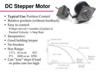
Major types of dc motors • Self excited dc motor • Series dc motor • Shunt dc motor • Compound dc motor • Separately excited dc motor • Permanent magnet dc motor
Rf Ra ia Ea VT (dc supply) M Series motors • Series motors connect the field windings in series with the armature. • Series motors lack good speed regulation, but are well-suited for high-torque loads like power tools and automobile starters because of their high torque production and compact size.
Pcf=ia2Rf P Pin= VTiL Pm Pout Pca=ia2Ra P is normally given Pin = Pout + total losses Where, Pca =armature copper loss Pcf =field copper loss P=stray, mech etc Pm= Ea ia Series Motor Power Flow Diagram
Rf Ra ia Ea VT (dc supply) M Series Motor (cont) • Example 1: A dc machine in Figure 1 is consumed a 6.5kW when the 12.5 A of armature current is passing thru the armature and field resistance of 3.3 and 2.0 respectively. Assume stray losses of 1.2kW. Calculate a) terminal voltage, VT b) back emf, Ea c) net torque if the speed is at 3560rpm d) efficiency of the machine [520V, 453.75V, 12N-m, 68.8%] Figure 1
Rf Ra ia Ea VT (dc supply) M Series Motor (cont) • Example 2: A 600V 150-hp dc machine in Figure 2 operates at its full rated load at 600rpm. The armature and field resistance are 0.12 and 0.04 respectively. The machine draws 200A at full load. Assume stray losses 1700W. Determine a) the armature back emf at full load, Ea b) developed/mechanical power and developed/mechanical torque c) assume that a change in load results in the line current dropping to 150A. Find the new speed in rpm and new developed torque. {Hint: Ea=K1K2ia} Figure 2 [568V, 113.6kW, 1808Nm, 811.27rpm, 1017Nm]
ia iL Ra if Rf Ea VT (dc supply) M Shunt motors • Shunt motors use high-resistance field windings connected in parallel with the armature. • Varying the field resistance changes the motor speed. • Shunt motors are prone to armature reaction, a distortion and weakening of the flux generated by the poles that results in commutation problems evidenced by sparking at the brushes. • Installing additional poles, called interpoles, on the stator between the main poles wired in series with the armature reduces armature reaction.
Pcf=if2Rf P Pin=VTiL Pm Pout Pca=ia2Ra P is normally given Pin = Pout + total losses Where, Pca =armature copper loss Pcf =field copper loss P=stray, mech etc Pm= Ea ia Shunt Motor (power flow diagram)
Shunt Motor • Example : • A voltage of 230V is applied to armature of a machines results in a full load armature currents of 205A. Assume that armature resistance is 0.2. Find the back emf, net power and torque by assuming the rotational losses are 1445W at full load speed of 1750rpm. [189V, 37.3kW, 203.5Nm]
Rf2 ia iL Ra if Rf1 Ea VT (dc supply) M Compound motors • the concept of the series and shunt designs are combined.
Pca=ia2Ra Pcf2=ia2Rf2 P Pin=VTiL Pm Pout Pcf1=if2Rf1 P is normally given Pin = Pout + total losses Where, Pca =armature copper loss Pcf =field copper loss P=stray, mech etc Pm= Ea ia Compound motor (power flow diagram)
Separately Excited Motor • There is no direct connection between the armature and field winding resistance • DC field current is supplied by an independent source • (such as battery or another generator or prime mover called an exciter)
Ra La Rf ia If Lf Vf VT Ea M Separately Excited Motor (Cont) Circuit analysis: Where p= no of pole pair n= speed (rpm) Z=no of conductor =Flux per pole (Wb) C= no of current/parallel path =2p (lap winding) =2 (wave winding) KVL:
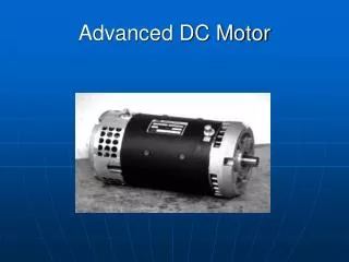
Permanent Magnet motors • PMDC is a dc motor whose poles are made of permanent magnets. • Do not require external field circuit, no copper losses • No field winding, size smaller than other types dc motors • Disadvantage: cannot produce high flux density, lower induce voltage
m Starting torque =0 n=0 n n nNL Speed Control for shunt motor and separately excited dc motor • Torque –speed characteristic for shunt and separately excited dc motor
Speed Control for shunt motor and separately excited dc motor • By referring to the Torque –speed characteristic for shunt and separately excited dc motor • note that, there are three variables that can influence the speed of the motor,V If Ra • Thus, there are three methods of controlling the speed of the shunt and separately excited dc motor, • Armature terminal – voltage speed control • Field speed control • Armature resistance speed control Variables
Speed Control for shunt motor and separately excited dc motor • Armature resistance speed control • Speed may be controlled by changing Ra • The total resistance of armature may be varied by means of a rheostat in series with the armature • The armature speed control rheostat also serves as a starting resistor. • From -n characteristic, Will be changed
m Ra1 Ra1 < Ra2< Ra3 Ra2 Ra3 n n3 n2 n1 nNL Speed Control for shunt motor and separately excited dc motor • Torque –speed characteristic
Speed Control for shunt motor and separately excited dc motor • Advantages armature resistance speed control: • Starting and speed control functions may be combined in one rheostat • The speed range begins at zero speed • The cost is much less than other system that permit control down to zero speed • Simple method • Disadvantages armature resistance speed control : • Introduce more power loss in rheostat • Speed regulation is poor (S.R difference nLoaded & nno loaded) • Low efficiency due to rheostat
Speed Control for shunt motor and separately excited dc motor • Field Speed Control • Rheostat in series with field winding (shunt or separately ect.) • If field current, If is varied, hence flux is also varied • Not suitable for series field • Refer to -n characteristic, • Slope and nNL will be changed
m n n3 n1 n2 nNL3 nNL2 nNL1 Speed Control for shunt motor and separately excited dc motor • Torque –speed characteristic If1 < If2< If3 1< 2 < 3 Base speed
Speed Control for shunt motor and separately excited dc motor • Advantages field speed control: • Allows for controlling at or above the base speed • The cost of the rheostat is cheaper because If is small value • Disadvantages field speed control : • Speed regulation is poor (S.R difference nLoaded & nno loaded) • At high speed, flux is small, thus causes the speed of the machines becomes unstable • At high speed also, the machines is unstable mechanically, thus there is an upper speed limit
Speed Control for shunt motor and separately excited dc motor • Armature terminal – voltage speed control • Use power electronics controller • AC supply rectifier • DC supply chopper • Supply voltage to the armature is controlled • Constant speed regulation • From -n characteristic, • C and nNL will be change • Slope constant
Speed Control for shunt motor and separately excited dc motor • Torque –speed characteristic m V3< V2< V1 n n3 n2 n1 nNL1 nNL2 nNL3
Speed Control for shunt motor and separately excited dc motor • Advantages armature terminal voltage speed control: • Does not change the speed regulation • Speed is easily controlled from zero to maximum safe speed • Disadvantages armature terminal voltage speed control : • Cost is higher because of using power electronic controller
FACTORS AFFECTING THE PERFORMANCE OF DC MACHINE • There are two factors affecting the performance of dc machine • Armature reaction • Armature inductance
Armature Reaction • Definition of armature reaction: • It is the term used to describe the effects of the armature mmf on the operation of a dc machine as a "generator" no matter whether it is a generator or motor. • It effects both the flux distribution and the flux magnitude in the machine. • The distortion of the flux in a machine is called armature reaction • Two effects of armature reaction: • Neutral Plane Shift • Flux Weakening
Armature Reaction • Effect on flux distribution:Neutral plane shift • When current is flowing in the field winding, hence a flux is produced across the machine which flows from the North pole to the South pole. • Initially the pole fluxis uniformly distributed and the magnetic neutral plane is vertical
Armature Reaction • Effect on flux distribution:Neutral plane shift • effect by the air gap on the flux field causes the distribution of flux is no longer uniform across the rotor. • There are two points on the periphery of the rotor where B= 0.
Armature Reaction • Effect on flux distribution:Neutral plane shift • when a load connected to the machines a resulting magnetic field produced in the armature • If the armature is rotated at a speed by an external torque each armature coil experiences a change in flux t as it rotates. • A voltage is generated across the terminals of each winding according to the equation e = t
Armature Reaction • Effect on flux distribution:Neutral plane shift • Both rotor and pole fluxes (flux produced by the field winding and the flux produced by the armature winding) are added and subtracted together accordingly • The fields interact to produce a different flux distribution in the rotor. • Thus, the flux on the middle line, between the two field poles, is no longer zero.
Armature Reaction • Effect on flux distribution:Neutral plane shift • The combined flux in the machine has the effect of strengthening or weakeningthe flux in the pole.Neutral axis is therefore shifted in the direction of motion. • The result is current flow circulating between the shorted segments and large sparks at the brushes. The ending result is arcing and sparking at the brushes. • Solution to this problem: • placing an additional poles on the neutral axis or mid-point that will produce flux density component, which counter-acts that produced by the armature.
Armature Reaction • Effect on flux magnitude:Flux Weakening • Most machine operate at saturation point • When the armature reaction happen, at location pole surface: • The add of rotor mmf to pole mmf only make a small increase in flux • The subtract of rotor mmf from pole mmf make a large decrease in flux. • The result is the total average flux under entire pole face is decreased. • This is called Flux Weakening d –flux decrease under subtracting section of poles
Armature Inductance • When rotor turns, thus we have inductance value, e1 = L(di/dt). Let say current ia1. • That means, we have ability to store energy • If the machine is turn ‘off’, thus, e1 will decreased. This will affect the current as well. Say ia2. • When the machine is turn ‘on’ again, it will produce e2 while e1 is still inside. The current now is reversed direction from previous (decreasing) current. • Thus, it will cause sparking resulting the same aching problem caused by neutral plane shift.