Download
1 / 15
1.35k likes | 3.92k Vues
DC MOTOR SPEED CONTROL. 1. Introduction Permanent Magnet DC motors are increasingly being used in a wide spectrum of applications such as domestic equipments, automobiles, information technology equipment, industries, public life appliances…….

E N D
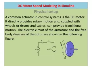
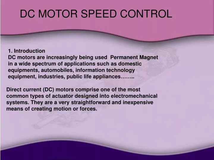
DC MOTOR SPEED CONTROL 1. Introduction Permanent MagnetDC motors are increasingly being used in a wide spectrum of applications such as domestic equipments, automobiles, information technology equipment, industries, public life appliances…….. Direct current (DC) motors comprise one of the most common types of actuator designed into electromechanical systems. They are a very straightforward and inexpensive means of creating motion or forces.
DC MOTOR SPEED CONTROL Permanent magnetDC motors are constructed out of a number of components. The exact design and materials vary with each type of motor and depend on the application and constraints, but several elements are common to most. The construction generally consists of a stator, which is made up of powerful permanent magnets that generate a static magnetic field; a rotor which carries the armature (also known as the windings or coils) and the commutatator, and rotates in the bearings that support it; and a housing that holds the stator, rotor bearing supports and brushes in a fixed relationship to one another.
DC MOTOR SPEED CONTROL Figure 1.1: Permanent Magnet Brushed DC Motor Construction, Components and Nomenclature
DC MOTOR SPEED CONTROL Type speed control : 1-analog speed motor control 2-digital speed motor control 1-ANALOG SPEED MOTOR CONTROL open loop control : Basically, there are three ways to vary the speed of DC motors: 1. With the use of mechanical gears to achieve the desired speed. This method is generally beyond the capability of most hobbyist home workshops.
DC MOTOR SPEED CONTROL 2. Reducing the motor voltage with a series resistor. However this is inefficient (energy wasted in resistor) and reduces torque. The current drawn by the motor increases as the load on the motor increases. More current means a larger voltage drop across the series resistor and therefore less voltage to the motor. The motor now tries to draw even more current, resulting in the motor "stalling". 3. By applying the full supply voltage to the motor in bursts or pulses, eliminating the series dropping effect. This is called pulse width modulation (PWM)
DC MOTOR SPEED CONTROL in our project we used kit 166 in this kit (PWM) is used Short pulses means the motor runs slowly; longer pulses make the motor run faster. This kit allows controlling the speed of a DC motor in both the forward and reverse direction. The range of control is from fully OFF to fully ON in both directions. HOW IT WORKS (refer to schematic) The circuit can be broken down in four parts: 1. Motor control – IC1:A 2. Triangle wave generator – IC1:B 3. Voltage comparators – IC1:C and D 4. Motor drive – Q3-6
DC MOTOR SPEED CONTROL Let us start with the motor drive section, based around MOSFETs Q3-6. Only two of these MOSFETs are on at any one time. When Q3 and Q6 are ON then current flows through the motor and it spins in one direction. When Q4and Q5 are ON the current flow is reversed and the motor spins in the opposite direction .
DC MOTOR SPEED CONTROL Opamps IC1:C and IC1:D are configured as voltage comparators. The reference voltage that each triggers at is derived from the resistor voltage divider of R6, R7 and R8 . Opamp IC1:B is set up as a triangle wave generator and provides the trigger signal for the voltage comparators. The frequency is approximately the inverse of the time constant of R5 and C1 – 270Hz for the values used . The DC offset voltage is controlled by the potentiometer P1 by IC1:A, which is configured as a voltage follower .
DC MOTOR SPEED CONTROL Closed loop speed control system Even though the steady output speed of the armature-controlled DC motor is proportional to the applied voltage in the open loop, the speed obtained may vary with applied load torques. To achieve better speed regulation, that is to be able to maintain the same speed in the face of fluctuating loads, and to achieve a faster response . There is often the need for a speed controller for small DC motors, so We have investigated the possibility of developing a speed controller that uses the motor as the tachometer. This uses the motor as a generator
DC MOTOR SPEED CONTROL 2-DIGITAL SPEED MOTOR CONTROL The main objectives in this section are to create and calibrate sensors to set the desired speed and measure the actual speed . The project aims at interfacing these sensors with a DC motor. The project also intends to familiarize us with the various control laws of an open as well as a closed loop control system. This is accomplished by interfacing with dc motor as generator tachometer , Op-Amp, DC motor, and use of PWM command. The LCD display is used to read the duty cycles and RPM of the motor resulting from the control action. The keypad is used to input the desired speed and direction .
DC MOTOR SPEED CONTROL Tachometer Output Measurement of the motor’s rotational speed is done by uses the motor as tachometer. This uses the motor as a generator - for example small DC permanent magnet motors are often used as DC generators in servo systems - with the generated voltage , the output voltage from the tachometer is (0-7.5). but we are faced with two problem : the first problem is the output voltage from the tachometer is (0-7.5) volt and at this volt the pic will be damage so we transfer this voltage to 5 volt ,and we are make the desired process to deal with this volt as 7.5 volt in the software code
DC MOTOR SPEED CONTROL The second problem after the dc motor start rotation the feedback tachometer generate dc voltage from (0 to 7.5) volt and when the dc motor rotate in the other direction the tachometer generate dc voltage from (0 to -7.5) volt but if negative voltage appeared on the leg of the picthen the pic will be damaged, andso to overcome this problem we installed two diods on the input of the pic such that prevent the leg of the pic output current , then the system will be calculate the difference voltage from the output of the tachometer and calculate the difference between the desired voltage .and actual voltage
DC MOTOR SPEED CONTROL Keypad Interface 4*3 keypad is used for entering information needed to operate the motor controller. The motor speed desired speed , the direction of rotation , and the deadband for on-off control can all be entered from the keypad. LCD Output 2x16 character LCD display is used to output data from the microcontroller. It is run using data in parallel from either 4 or 8 data lines. It requires 6 data lines in this mode to operate, which is a significant portion of the 16 available I/O lines of the microcontroller, in our project we displayed the desired speed and actual speed and the direction of rotation .
DC MOTOR SPEED CONTROL There are three PID controllers in this design proportional controller , integral controller and derivative controller ,and system will be deal with this parameters as this relation : Start : error= desired Speed – actual Speed dt integral= integral +error * derivative= (error – Previous Error)/dt output= kp * error + ki * integral + kd * derivative Previous Error=error