Download
1 / 41
410 likes | 539 Vues
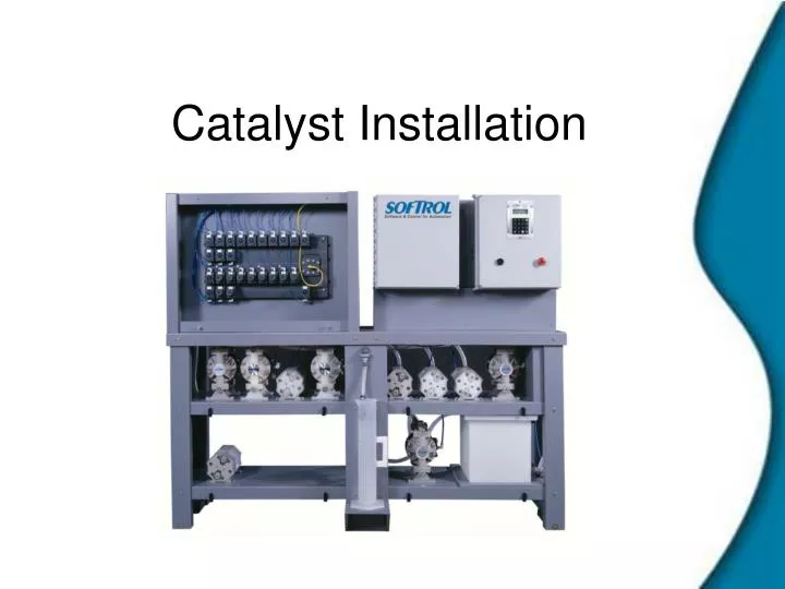
Catalyst Installation. Location, Location, Location. The Catalyst should be located a central as possible to all the machines. The distance from the day tanks or drums should be less than 30 ft. Minimize the length and elevation to the machines. ¾” Hose = 2.7 gal. per 100ft.

E N D
Location, Location, Location • The Catalyst should be located a central as possible to all the machines. • The distance from the day tanks or drums should be less than 30 ft. • Minimize the length and elevation to the machines. • ¾” Hose = 2.7 gal. per 100ft. • ½” Hose= 1.0 gal. per 100ft. • Maximum recommended distance to machines is 200 ft for ¾” and 400 ft for ½”.
Utilities Air- • 8 SCFM @ 90 PSI- Clean Dry Air. • ½” Line recommended, 3/8” OD push to connect fitting on Catalyst. • Catalyst will not pump chemical if air pressure falls below 65 PSI.
Utilities Water- • 3 GPM @ 20- 40 PSI. • Temperature 70-110 deg F. • ½” hose barb connection. • Can be used with tempering valve- not supplied with system.
Utilities Electrical- • 5 amps at 120 VAC • 15 ft electrical cord with system. • Circuit should be dedicated to system. • Hub requires 5 amps at 120 VAC as well.
Utilities Drain- • ½” Back-Flush drain connection. • ½” Overflow drain connection. • Overflow is gravity drain, back-flush is pressurized. • Do not connect drains together!
Chemical Connections The inlet lines to the pumps must have adequate strainers (#12 Mesh minimum). These may be incorporated with drum wands (available from Softrol) or can be piped inline. It is recommended that if the strainers are piped inline, a shutoff valve be located on either side as to allow for easier cleaning.
Chemical Connections • The chemical pumps should be tightened to the proper torque before the chemicals are connected. Use 7/16” nut driver. Torque from bolt head. This is on the side of the air inlet. Tighten all 6 bolts. Use a ½” wrench. Torque both sides Tighten ALL bolts and nuts.
Chemical Connections Inlets for Pumps ½” Inlet for small pumps ¾” Inlet for large pumps
Machine Connections Outlets to machines
Machine Connections-Multiple systems **** Check valves should be as close together as possible to avoid contamination ****
Catalyst Configuration From the “Waiting for Chemical Injection Request!” display, enter a valid level 7 password (please refer to Passwords). 1=Setup 2=Program 3=Maint. 4=Calib. 5=Totals 6=Clock Selection? 0=exit Select 1=Setups 1=Watchdogs/Setups 2=Chemical Setups Select 1=Watchdogs/Setups 1=Machine Setup 2=Maintenance Setup 3=Clear Ram Vocabs 4=Passwords 0=exit Select 1=Machine Setup
Catalyst Setups AutoChemFlush This setup answered in seconds is the amount of time the Catalyst will flush the system with water after each chemical injection. The Catalyst will read the time on the machine and use the time that is the greatest. Chems 9-12 Auto If answered YES, the Catalyst will turn on the chemical outputs for chemicals 9 through 12. Answer No if the Catalyst will process with automatic chemicals 1 thru 8 only. Chems 13-16 Auto If answered YES, the Catalyst will turn on the chemical outputs for chemicals 13 through 16. Answer No if the Catalyst will process with automatic chemicals 1 thru 12 only.
Catalyst Setups Flow Sensors This setup tells the Catalyst to use the flow sensor input Chemical Watchdog This is the time in mm:ss the user defines is sufficient for a Catalyst to hold itself while dispensing the chemical. Prompt Weight This indicates whether the operator wishes to prompt the weight of the load before the start of each manual formula. This allows the operator to use ratio metric chemical additions. This will most likely be set to NO. Signal Mute Time This is the time in mm:ss the user defines how long a signal will be ignored when pressing the CLR key.
Catalyst Setups First Washer ID This setup informs the Catalyst the ArcNet networking ID of the first washer to be serviced. Last Washer ID This setup informs the Catalyst the ArcNet networking ID of the last washer to be serviced. Preferred ID Lo This setup is used to assign the lowest ArcNet networking ID that determines the preferable range for the Catalyst to inject chemicals. Decisions by the Catalyst will be given preference according to the programmed range. Preferred Range Hi This setup is used to assign the highest ArcNet networking ID that determines the preferable range for the Catalyst to inject chemicals. Decisions by the Catalyst will be given preference according to the programmed range.
How the Catalyst Assigns Machines to Outlet Valves 1st Machine ID The valves are then numbered consecutively until the last machine is reached.
Redundant Systems Preferred Range CATALYST #1 Preferred Range 1-8 CATALYST #2 Preferred Range 9-16 MACHINE ID 5 Chemical Injection Required
Redundant Systems Preferred Range CATALYST #1 Preferred Range 1-8 Injecting to Machine #2 CATALYST #2 Preferred Range 9-16 MACHINE ID 5 Chemical Injection Required
Redundant Systems Preferred Range CATALYST #1 Preferred Range 1-8 Injecting to Machine #2 In Queue until a Catalyst is available CATALYST #2 Preferred Range 9-16 MACHINE ID 5 Injecting to Machine #9 Chemical Injection Required
Mounting the Interface • The interface should be mounted in close proximity to the machine. • The area should be free from excess vibration and protected from slings, carts, and indiscriminate wash aisle personnel. • If tracking weight, the interface should be mounted in a easy to access location.
Powering the Interface Requires 24 VAC transformer with a 12 volt center tap. (provided with interface) Requires 24 VDC. Will be supplied from the Catalyst.
Wiring the Interface Accepts 8 binary inputs. 24 VAC/VDC Standard- 120/240 VAC is available. White Input Modules= 24v Yellow Input Modules= 120v or 240v Dry contact NO/NC for timer hold Relay for Machine on- 24 VAC Standard
Wiring CataPulse Interface Accepts 8 binary inputs. Integrated 24 VAC/VDC Inputs. 120 VAC is available. Requires input card mounted in Machine. Dry contact NO/NC for timer hold Relay for Machine on- 24 VAC Standard
Interface Configuration-Old Interface • From the “Waiting for Chemical Injection Request!” display, enter a valid level 7 password (please refer to Passwords). 1=Setups 2=Program 3=Maint. 4=Calibrate 5=Totals 6=Clock Selection? 0=exit • Select 1=Setups 1=Watchdogs/Setups 2=Chemical Setups • Select 1=Watchdogs/Setups 1=Machine Setup 2=Maintenance Setup 3=Clear Ram Vocabs 4=Passwords 0=exit • Select 1=Machine Setup
Interface Configuration Metric System = No Manual Buttons = No Momentary Load = No All Chems Manual = No Auto Chem Flush = Varies Chems 9-12 Auto = Varies Chems 13-16 = Varies One way w/ Chems = Yes Chems Forward = Yes Drain Delay = 8 Extract Retry = No Unload Normally = Yes 3rd Water Valve = No Second Drain = No Chemical Watchdog = 8:00 Drain/Fill Watchdog = 4:00 Steam Inj Watchdog = 8:00 Cooldown Watchdog = 8:00 Level Halt Hi = 65.0 “ Temp Halt Low Limit = 0 Temp Halt Hi Limit = 212 Level Deadband = 1.0
Interface Configuration Important Setups • Chemical Watchdog-(mm:ss) Time that the interface will allow for the Catalyst to service an injection request before it will alarm. Allow more time for systems with a large machine to Catalyst ratio. • AutoChem Flush-(5-99 sec) This setup tells the Catalyst how long to flush the chemical to the machine. The further away from the Catalyst the machine is, the longer the flush time. • Prompt Weight-(YES or NO) This will allow an operator to enter the weight at the beginning of the formula for reporting or ratiometric chemical addition purposes. • Signal Mute Time- (mm:ss) Time interface will silence alarm when CLR is pressed • LAN ID-(1-254) This is the ID of the machine. This should correspond to the machine outlet valve to which the machine is plumbed. Set with dip switches on Catapulse. Prompt Weight = No/Yes Supply Disp 6 & 7 = No KVA Lockout = No Slow Drain = No Maximum Volume = 0 Min. Steam Gradient = 0 Signal Mute Time = 5:00 Full Baud Rate = Yes Multidrop Net = Yes LAN Member ID = Varies
Interface Configuration-CataPulse Chemical Watchdog- (mm:ss) Time that the interface will allow for the Catalyst to service an injection request before it will alarm. Allow more time for systems with a large machine to Catalyst ratio. AutoChem Flush- (5-99 sec) This setup tells the Catalyst how long to flush the chemical to the machine. The further away from the Catalyst the machine is, the longer the flush time. Prompt Weight- (YES or NO) This will allow an operator to enter the weight at the beginning of the formula for reporting or ratiometric chemical addition purposes. Signal Mute Time- (mm:ss) Time interface will silence alarm when CLR is pressed LAN ID- (1-254) This is the ID of the machine. This is set with dip switches on Catapulse main board.
Interface Configuration Latch Time Some washers cannot give simultaneous chemical signals or even more than two signals per step. These include a Milnor EP Plus and the Braun. To help these machines identify formulas, we must use the feature known as latch time. To set the latch time: From the “Waiting for Chemical Injection Request!” display, enter the password- 273685 1=Setup 2=Program 3=Maint. 4=Calib. 5=Totals 6=Clock Selection? 0=exit Select 1=Setups 1=Watchdogs/Setups 2=Chemical Setups Enter 935483 This will take the interface to a new setup screen. Press enter to scroll through the setups until Latch time is reached. The default time is 20 seconds. Set the appropriate latch time and press enter to continue through the setups. Exit through the main screen. Use the Catalyst schematic for a reference on what the Latch time should be.
Latch Time Latch time works in the following manner- Ex- Formula 7 on a Braun Step 1- Chemical 1 on for 5 sec. Chemical 2 on for 5 sec. Step 2- Chemical 3 on for 5 sec. Chemical 7 on for 5 sec. This will Identify formula 7 to the interface.
Machine Configuration (for Catalyst Injection) Important Setups • AutoChem Flush-(5-99 sec) This setup tells the Catalyst how long to flush the chemical to the machine. The further away from the Catalyst the machine is, the longer the flush time. • Chemical Watchdog-(mm:ss) Time that the interface will allow for the Catalyst to service an injection request before it will alarm. Allow more time for systems with a large machine to Catalyst ratio. • Prompt Weight-(YES or NO) This will allow an operator to enter the weight at the beginning of the formula for reporting or ratiometric chemical addition purposes. • LAN ID-(1-254) This is the ID of the machine. This should correspond to the machine outlet valve to which the machine is plumbed. • Catalyst Inject- (YES) This tells the machine to execute a chemical request via the network rather than use the chemical outputs.
Arcnet Installation • Maximum 255 nodes ID 1-255 • Can be Bus or Star configuration • Can use Coax (RG-62), Twisted pair (Cat 5) or Fiber-optic (Star configuration only) • Communication speed up to 5 MegaBaud (very fast compared to RS-485) • All ends of network must be terminated. • Cannot have duplicate IDs • Cannot have terminators in middle of line or “double terminators”
Bus Configuration T MACHINE MACHINE MACHINE MACHINE HUB T MACHINE MACHINE MACHINE MACHINE • A series of machines are “daisy chained” from the hub. • Maximum of 8 machines or Nodes per line. • Each line must end in a terminator. • Maximum length of line- 1000’ Coax, 400’ twisted pair. • Most common for Catalyst networks.
Star Configuration MACHINE MACHINE HUB MACHINE MACHINE • Each machine or node is connected directly to the hub. • Maximum of 4 machines or Nodes per Hub card. • Each machine or node must have a terminator. • Maximum length of line- 1000’ Coax, 400’ twisted pair. • Most common for Automation networks.
Bus Configuration vs. Star Configuration • Bus configuration is less expensive- requires less hub cards and less cable to install, therefore it can be easier to install. • Star configuration is easier to troubleshoot. • Star configuration can be more immune to “electronic noise” in the plant. Coax vs. Twisted Pair • Coax can be easier to install- Must be careful pulling Cat 5 • Coax can be easier to troubleshoot. • Twisted pair can be more noise immune. • Twisted pair is becoming less expensive.
Specifications Coax- RG-62 with 93 ohm terminator. Do not use RG 58 or a 50 ohm terminator. Twisted Pair Cat 5 twisted pair. 75 ohm characteristic impedance Commonly called Ethernet Cable. Should be stranded instead of more common solid core.
Guidelines for Networks • Be careful when pulling the cable- it can be stretched and cause problems. • Avoid running in close proximity to objects that can generate electrical noise- These include- Motors, Variable Speed Drives, High voltage lines, electrical panels, and high voltage lights. • If you have to cross a high voltage line, cross perpendicular to the voltage line. • Do not pull the wire taught and secure- Expansion and contraction with change in temperature can cause problems.