Download

1 / 43
440 likes | 580 Vues
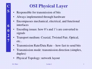
OSI Physical Layer. Network Fundamentals – Chapter 8. What Will we Learn from chapter 8?. Physical layer protocols and services in supporting communication across data networks The role of signals used to represent bits as a frame transported across the local media

E N D
OSI Physical Layer Network Fundamentals – Chapter 8
What Will we Learn from chapter 8? • Physical layer protocols and services in supporting communication across data networks • The role of signals used to represent bits as a frame transported across the local media • The purpose of Physical layer signaling and encoding used in networks • Basic characteristics of copper, fiber and wireless network media
OSI Model – PDU– protocol - hardware • Layer 7 data • Layer 6 data • Layer5 data • Layer 4 segments TCP,UDP • Layer 3 packets IP routers • Layer 2 frames MAC hubs, bridges, switches • Layer 1 bits amplifiers, repeaters *PDU – Protocol Data Unit (may contain control information) Layers 1 thru 4.
Modulation • A technique for processing signals in which two waves are combined to produce a wave that possesses characteristics of both and can be decoded to separate these characteristics. • Information wave - the wave containing the signal you want to transmit. • Carrier wave - the wave that is modulated, and whose properties are constant and known to both the sender and receiver. • Guided waves - waves that are bound to a carrier wave’s frequency.
Modulation • Modulator - the device that imposes the message signal on the carrier signal at the transmission end. • Demodulator - separates the message from the carrier signal at the receiving end. • Modem - a device used to convert digital into analog signals and analog into digital signals.
Amplitude Modulation t =>
Frequency Modulation • A method of modulation in which the frequency of the carrier signal is modified by the addition of the message signal. • Frequency shift keying (FSK) - when FM signals are converted into digital signals, the differing frequencies are conveyed as either 0s or 1s.
Pulse Code Modulation (PCM) • The process of converting analog signals into digital signals • Sampling - the first step in converting analog signals to digital signals is to measure the amplitude of an analog signal at multiple instants. • The higher the sampling rate, the more closely the digital signal resembles the original analog signal.
10base 2 – 10base 5 10 base 2 and 10 base 5 are terms used to describe coaxial cables. 10 is the speed 10 mbps base- signaling(baseband) 2 or 5 denotes the max length that can be used. 200 meters or 500
10base-T – 100base-T – 1000base-T 1xxx base T used to describe twisted pair cabling 1xxx is the speed in mbps base- signaling (baseband) The T stands for twisted pair
Fiber • For Gigabit Ethernet, industry offerings include these types of wiring: • 1000BASE-SX(a short laser wavelength on multimode fiber optic cable for a maximum length of 550 meters) • 1000BASE-LX/LH(a long wavelength for a "long haul" fiber optic cable for a maximum length of 10 kilometers) • 1000BASE-ZX (an extended wavelength single-mode optical fiber for up to 100 kilometers) • 1000BASE-CX(two pairs of 150-ohm shielded twisted pair cable for a maximum length of 25 meters) • 1000BASE-T(four pairs of Category 5 unshielded twisted pair cable for a maximum length of 100 meters)
Twisted Pair Outer Jacket Plastic insulation Outer Jacket Foil shield Unshielded twisted pair (four pair) Twisted Pairs Braided shield Outer Jacket Twisted Pair Overall shield Shielded twisted pair (two pair) ScTP (a hybrid UTP) shielded Characteristics & Uses of Network Media
D C A B Coaxial cable anatomy
Single-mode Multimode Multimode Multimode Buffer coating 10 - 125 microns 50 - 125 microns 62.5 - 125 microns 100 - 140 microns Core Cladding Fiber-optic cable anatomy
Single-Mode Multimode ST Connector SC Connector Single and Multimode Fiber-optical connectors
What Did I Learn from chapter 8? • Physical layer protocols and services in supporting communication across data networks • The role of signals used to represent bits as a frame transported across the local media • The purpose of Physical layer signaling and encoding used in networks • Basic characteristics of copper, fiber and wireless network media
OSI Physical Layer Next Ethernet