Download
1 / 67
670 likes | 694 Vues
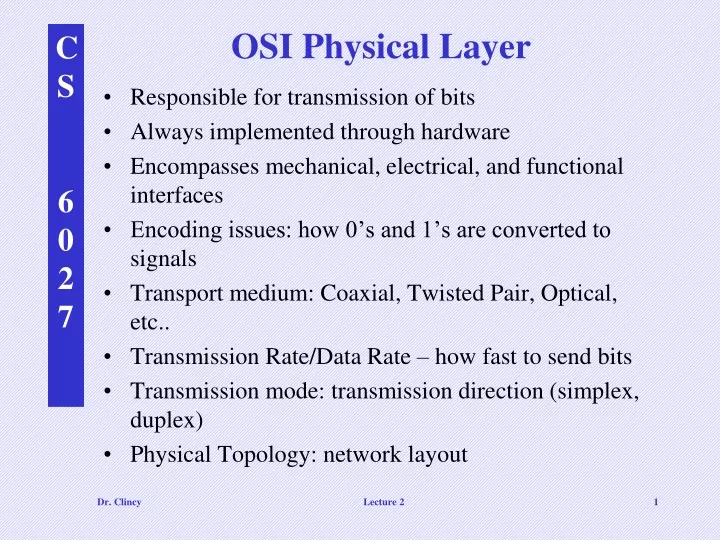
OSI Physical Layer. Responsible for transmission of bits Always implemented through hardware Encompasses mechanical, electrical, and functional interfaces Encoding issues: how 0’s and 1’s are converted to signals Transport medium: Coaxial, Twisted Pair, Optical, etc..

E N D
OSI Physical Layer • Responsible for transmission of bits • Always implemented through hardware • Encompasses mechanical, electrical, and functional interfaces • Encoding issues: how 0’s and 1’s are converted to signals • Transport medium: Coaxial, Twisted Pair, Optical, etc.. • Transmission Rate/Data Rate – how fast to send bits • Transmission mode: transmission direction (simplex, duplex) • Physical Topology: network layout Lecture 2
Actually sends the packets (groups of frames) from node to node using a routing algorithm Network Layer Data Link Layer Takes raw data (bits) and transform them into frames, error control, etc. Transmit and receive the raw data (bits) Physical Layer OSI Data Link Layer • Responsible for error-free, reliable transmission of data • Framing, Flow control, Error control (detection/correction) and Assess Control • Makes use of physical address because with in the same network Lecture 2
OSI Network Layer • Responsible for routing of messages through networks • Concerned with type of switching used (circuit v. packet) • Handles routing among different networks • NOTE: with in the same network, only the DATA LINK layer is needed – amongst multiple networks, the NETWORK LAYER is needed • No need for routing with in the same network (LAN) • Routing across “internetworks” • Makes use of logical address vs physical address because not with in same network Lecture 2
OSI Network Layer Lecture 2
OSI Transport Layer • Isolates messages from lower and upper layers • Breaks down message size (segmentation) (down) and performs re-assembly (up) • Monitors quality of communications channel (oversee all hops) • Selects most efficient communication service necessary for a given transmission (could change over hops) • Flow and Error control for Source and Sink Lecture 2
OSI Session Layer • Establishes logical connections between systems (up/down) • Manages log-ons, password exchange, log-offs (up/down) • Terminates connection at end of session (up/down) Lecture 2
OSI Session Layer Lecture 2
OSI Presentation Layer • Provides format and code conversion services • Examples • File conversion from ASCII to EBDIC • Invoking character sequences to generate bold, italics, etc on a printer • The source and sink could operate using different encoding schemes – the presentation layer makes the translations • Security • Compression Lecture 2
OSI Application Layer • Provides access to network for end-user (end-user being a human being or software application) • User’s capabilities are determined by what items are available on this layer (ie. remote log-in, file transfer, email service, directory service, etc.) Lecture 2
What happens at the End and Intermediate Nodes ? Rx Tx 7 Intermediate Nodes 3 1 1 B C Q T A Z Lecture 2
Recap - OSI’s Layered Approach • between different layers on the same node or stack (INTERFACE) • between similar layers on different nodes or stacks (PEER-TO-PEER PROCESSES) Lecture 2
An exchange using the OSI model Explain encapsulation and decapsulation Lecture 2
COMPLEXITY TO CONSIDER • Any particular node in an internetwork can be functioning as follows simultaneously: • Tx to other internetwork nodes • Rx from other internetwork nodes • Intermediate node to some other internetwork nodes Lecture 2
OSI in Action: Outgoing File Transfer • The File Transfer Program issues a command to the Application Layer • Application passes it to Presentation, which may reformat, encrypt, encode, compress, passes to Session (adds overhead) • Session requests a connection, passes to Transport (adds overhead) • Transport breaks file into chunks, adds error-checking and flow-control info, process-to-process, passes to Network (adds overhead) • Network selects the data’s route (internetworking), passes to Data Link (adds overhead) • Data Link adds error-control and flow-control info, passes to Physical (adds overhead) • Physical translates bits to signal and transmits the signal, which includes information added by each layer Lecture 2
OSI in Action: Incoming File Transfer • Physical receives signal and translates to bits, passes to Data Link • Data Link checks for errors and performs flow control on bits, formulates bits into some formation (frames), passes to Network • Network verifies routing (if intermediate node, determines next hop), passes to Transport • Transport checks for errors and performs flow control on the chunks, reassembles the chunks, passes to Session • Session determines if transfer is complete, may end session, passes to Presentation • Presentation may reformat, perform conversions, decode, decrypt, decompress, pass to Application layer • Application presents results to user (e.g. updates FTP program display) Lecture 2
Ch 3: Underlying Technologies Ch 2: TCP/IP and OSI Lecture 3 and 4 Lecture 3 and 4
How TCP/IP maps to OSI ?? Lecture 3 and 4
TCP/IP Model Explain Suite and Stack Concept SCTP Protocols for different underlying technologies – this is key Lecture 3 and 4
Explain communications at the physical layer Signal to bits translation and vice versa (note: digital data is different from digital signal) Lecture 3 and 4
Physical addresses • Physical address is also known as the link address • Physical address can be different sizes (depend on the network) • Unicast type physical addresses – single Rx • Multicast type physical address – multiple Rxs • Broadcast type physical address – all Rxs can pickup message Lecture 3 and 4
Physical Address Example Most local area networks use a 48-bit (6 bytes) physical address written as 12 hexadecimal digits, with every 2 bytes separated by a hyphen as shown below: 07-01-02-01-2C-4B A 6-byte (12 hexadecimal digits) physical address Lecture 3 and 4
Explain communications at the data link layer Framing – encapsulation - decapsulation Lecture 3 and 4
Explain communications at the network layer IP Addresses can be either unicast, multicast or broadcast types Going from network A physical address 10 to network P physical address 95. Can’t use the physical address because different networks The network layer address contains the uniqueness we need from source to sink. Network layer address is A-P Unit at this layer - datagram Lecture 3 and 4
IP Address Example An Internet address (in IPv4) is 32 bits in length, normally written as four decimal numbers (or 4 octal numbers), with each number representing 1 byte. How many bits is a byte ? A nibble ?? The numbers are separated by a dot. Below is an example of such an address. Call “dot notation” 132.24.75.9 Example of IPv6 Address (128 bits): Lecture 3 and 4
ADDRESSING We explained the physical address. We explained the need for an Internetworking (IP) address or Logical address Are the Physical and Logical addresses enough ????? Lecture 3 and 4
Addresses in TCP/IP Application Specific Address Converts to a part address Lecture 3 and 4
Relation- ship between layers and addresses in TCP/IP “Specific Addresses” Lecture 3 and 4
Port addresses Addresses of sending and receiving processes (j and k) Add IP address Overhead (H2, T2) added for what ? Lecture 3 and 4
Port Address Example As we will see in Chapters 11 and 12, a port address is a 16-bit address represented by one decimal number as shown below. 753 A 16-bit port address Lecture 3 and 4
Relation- ship between Layers, Addresses, and Units in TCP/IP Messages Segments Datagrams (Packets) Frames Bits Lecture 3 and 4 Signals
Ch 3: Underlying Technologies (1 of 3) Lecture #3 Lecture 3 and 4
Internet – Underlying Technologies • As we mentioned before, the Internet is an interconnection of “backbone” networks JOINED together via routers, gateways and switches • Before getting into the higher level protocols, let’s cover more concerning the underlying technologies. Let’s talk about LANS and WANS and etc… • Internet is comprised of LANs, Point-to-Point WANs and Switched WANs • We will cover LANS: Ethernet, Token Ring (not in book), Wireless and FDDI Ring (not in book) • We will cover Pt-to-Pt WANs: Telephony Modem, DSL, Cable/Modem, T-Lines and SONET • We will cover Switched WANs: X.25, Frame Relay and ATM Token Ring (not in book) FDDI Ring (not in book) Lecture 3 and 4
In putting these technologies in perspective Most of the technologies we are about to highlight could be covered as a full blown course – in some cases, multiple courses We will look at each technology from a high level in gathering a general appreciation and understanding of the technology Lecture 3 and 4
LOCAL AREA NETWORKS (LANS) • LAN – a data communication system connecting multiple INDEPENDENT devices such computers, servers, printers, etc.. • Covers up to a certain geographical area – typically within a building or campus • Some Popular LANs: Ethernet, Token Ring, Wireless type LANs, and ATM LANs • Ethernet LAN • Ethernet is the more popular LAN protocol • Designed in 1973 by Xerox • Started out with a 10 Mbps data rate (bus topology) • Today, 100 Mbps and 1 gigabit per second exist (gig=1000 Mbps) • IEEE 802.3 standard describes the Ethernet protocol Lecture 3 and 4
CSMA/CD • The 802.3 standard describes the CSMA/CD standard as the access method for the original Ethernet • CSMA/CD stands for carrier sense multiple access with collision detection. • The transport medium is shared – only one station or node can use the medium at a time • All stations can receive a sent frame however, only the destination station takes it in (the other stations drop the frame) • How can we make sure no two stations are using the transport medium at the same time ? If this happened, the 2 frames could “collide” • CSMA/CD solves this problem: • CSMA/CD Process • Every station has equal access to the medium • Station listens to or senses the medium before sending frame – if no data, it can send – if data exist, wait • Suppose 2 stations sense at the same time and find no data on the medium, crash will happen • In this case, all stations sense the collision and each Tx send a “jam signal” to delete the data it sent • Then each station waits a randomly amount of time and try it again – this prevents a second collision Notice that Station Z receives a collision signal 1 time period earlier than Station A Lecture 3 and 4
CSMA/CD • 3 factors relate to CSMA/CD • 1. Minimum frame length • 2. Data transmission rate • 3. Collision domain (maximum network distance) • The amount of time a station needs to wait in making sure no data is on the line) is minimum frame length divided by the data transmission rate. Why ?? (Speed=Distance/Time) – the larger the frame, the longer the time to wait – however, sensing is shorter) • Amount of time to send the smallest frame (ie. an 8 bit frame at 2 bps will take 8/2 = 4 seconds to send – therefore, need to wait ATLEAST 4 seconds) • This time is proportionate to the time it will take the first bit to travel the maximum network distance (collision domain). • Therefore, (max network distance)/(propagation speed) proportionate to (min frame length)/(transmission-rate) • Data transmission rate – data transfer rate – how fast to send a certain amount of bits from one device to another • For the original Ethernet: min frame size=520 bits, transmission rate=10 Mbps and the max network distance=2500 meters Lecture 3 and 4
Increasing Speed of Ethernet • Decrease collision domain • Increase minimum frame length Detect faster Larger frame Smaller frame Lecture 3 and 4
Ethernet layers • Ethernet’s data link layer is sub-divided into MAC Layer and LLC Layer • MAC Layer – media access control layer – controls the CSMA/CD access method. Also performs the “framing” work. • LLC Layer – logical link control layer – performs the error and flow control routines Lecture 3 and 4
Ethernet frame • The Ethernet frame consist of 7 fields: preamble, SFD, DA, SA, length/type of PDU, 802.2 frame (the actual data) and CRC • Frame doesn’t provide acknowledgment or “hand shaking” fields – unreliable medium • Preamble – alternating 1s and 0s t alert and synchronize the Rx • SFD – start field delimiter – signals the beginning of the frame • Destination address – contains the address of the next node( intermediate or Rx) • Source address – contains the address of the sending node (Tx or intermediate) • Length of protocol data unit – if less than 1518, defines the length up-and-coming data field – if greater than 1536, tells the protocol that uses the service • Data & padding – data encapsulated from higher layers – size ranges between 46 bytes to 1500 bytes • CRC – cyclic redundancy check – error detection info Lecture 3 and 4
Ethernet implementation Each device on an Ethernet network has a NIC (network interface card) Contains the physical address –ah ha, this is how I can change locations and still get emails • Ethernet addressing: • Unicast • Multicast • Broadcast • Some implementations of Ethernet: • 10BASE5 (thick ethernet) • 10BASE2 (thin ethernet) • 10BASE-T (twisted pair) • 10BASE-FL (fiber link) Connects host to medium and perform CSMA/CD British naval connector or bayonet nut connector – for coaxial cable Lecture 3 and 4
Ethernet implementation Lecture 3 and 4
Ethernet implementation Unshielded twisted pair Lecture 3 and 4
Ethernet implementation Lecture 3 and 4
Fast Ethernet implementation 100 Mbps Ethernet 2-wire type (100BASE-TX or 100BASE-FX) 4-wire type (only 100BASE-T4) To make faster, collision domain was decreased 10 fold (250 meters vs 2500 meters) Lecture 3 and 4
Fast Ethernet implementation Lecture 3 and 4
Fast Ethernet implementation Lecture 3 and 4
Gigabit Ethernet implementation Need for data rates higher than 100 Mbps resulted in a 1000 Mbps Ethernet called gigabit Ethernet Again, we had the choice to either decrease the collision domain or increase the minimum frame size Because 25 meters for the 100 Mbps Ethernet was short enough, the minimum frame size was increased to get the desired speed Another option is to do away with the CSMA/CD overhead by connecting every station to the hub using 2 separate paths (this will do away with collisions) – called full-duplex Ethernet Lecture 3 and 4
Gigabit Ethernet implementation Lecture 3 and 4
Ten-Gigabit Ethernet implementation Lecture 3 and 4
Token Ring LAN • Token Ring is a protocol defined by IEEE 802.5 • Use a token passing ACCESS method • Token Passing Method • During idle times (network not being used), a token circulates • The token is passed station to station until a station needs to send data • When the station sends it’s data, it holds the token • The data (or frame) circulates and get re-generated by each station • The Rx takes in and COPY the frame (based on destination address) • The data then continues back to the original Tx • Token is then release to circulate Lecture 3 and 4