Download
1 / 46
500 likes | 757 Vues
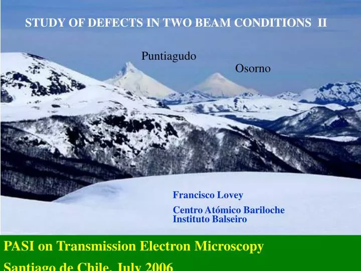
STUDY OF DEFECTS IN TWO BEAM CONDITIONS II. Puntiagudo. Osorno. Francisco Lovey Centro Atómico Bariloche Instituto Balseiro. PASI on Transmission Electron Microscopy Santiago de Chile, July 2006. Images of crystalline defects.

E N D
STUDY OF DEFECTS IN TWO BEAM CONDITIONS II Puntiagudo Osorno Francisco Lovey Centro Atómico Bariloche Instituto Balseiro PASI on Transmission Electron Microscopy Santiago de Chile, July 2006
Images of crystalline defects If the jth atom is moved from its position in the perfect crystal by a translation R(r), the potential at any point in the deformed crystal can be identified with the value of the potential at the position [r- R(r)] in the non deformed crystal. The potential in the deformed crystal can be expanded as a Fourier series, as for the non deformed crystal
The Fourier coefficient would change as To include the anomalous absorption
In the same way the coefficients of the wave function will change as
The basic eigenvalue equation No defects
The eigenvalue equation In the presence of defects can be written as
The wave function for the perfect crystals (including absorption) was (nearly normal incidence) In the presence of defects it becomes
Using the column approximation we shall assume that in each column From The wave functions can be expressed as The matrix Cdef=Q-1C makes Adef diagonal
Wave function in the presence of defects Nearly normal incidence, centrosymmetric crystals
The Howie-Whelan equations When g.R = 0, 1, 2,… the image of the defect vanishes
The Howie-Whelan equations can be written in an equivalent form by making the transformation:
The term plays the same role as Sg, representing the local curvature of the atomic planes. Equivalent form of the Howie-Whelan equations
Dislocations There are, basically, two types of dislocations: screw and edge dislocations. Dislocations combining both characteristics are called mixed dislocations Screw Edge
Where are the stresses (force per unit area) acting on the ith face in the jth direction The coefficients are the elastic constants The strains are defined as Elasticity The strain field of the dislocations is calculated on the base of the linear elasticity theory The fundamental equation of the linear elasticity yields
The displacement field around dislocations The uk’s functions are the component of the displacement fields at the coordinates x1, x2 and x3. Thus the uk’s are the components of the vector R(r) at the point r(x1, x2, x3). At rest there can not be torque on the element, so that provided there are not internal torques.
The elastic constants Contracted matrix notation as , where m and n are each indices corresponding to a pair of indices ij and kl, according to the following equivalency:
There are 81 elastic constants, however because of the symmetry only 21 elastic constants are independent.
Reduced 6x6 representation For cubic crystals Only three different elastic constants
In isotropic crystals only two elastic constants are needed: Shear modulus The Poisson modulus (Lamé constant)
r y x Displacement field of screw dislocation in an isotropic media Since only a shear deformation along the Burgers vector direction (z direction) on the (x,z) plane has been introduced, we have: ux = uy = 0. In an isotropic media the displacement uz increases uniformly with the angle , from uz = 0 for = 0 to uz = b for = 2 The extinction condition requires g.R = 0, 1, .. g.b = 0
Planar strain: uz = 0 and Displacement field of edge dislocation in an isotropic media The solution for the displacement field gives The extinction condition requires g.R = 0, 1, .. g.b = 0 g.(b^ez) = 0
Extinction in isotropic crystals Possible Burgers vectors [011] and [101]
Straight dislocations in anisotropic elastic media In mechanical equilibrium no net force can act on the volume element, giving the expression The x3 axis is parallel to the dislocation line direction. The elastic constants are referred to this system. In an infinite media the displacements, the strain, and stresses are all independent on x3 The partial differential equation has a solution of the type Computer electron micrographs and defects identification. Head, Humble, Clarebrough, Morton, Forwood, North Holland, 1973.
b = 100 g = 1-1 0 u = 1 1 1 b = 010 g = 1-1 0 u = 1 1 1 b = 001 g = 1-1 0 u = 1 1 1 Simulations COEFIC DE ABSORCION ANOMALA (ANO) 9.000000E-02 DESVIACION CONDICION DE BRAGG (W) 0.000000E+00 ESPESOR DE LA MUESTRA (THICK) 4.000000 COMIENZO DE LA INTEGRACION (START) -5.000000E-01 FINAL DE LA INTEGRACION (FINISH) 4.500000 SEPARACION DE DISLOCACIONES (SEP) 0.000000E+00 PARAMETROS DE RED (SIDE) 3.000000 3.000000 3.000000 NUM DEL 1er. VECTOR DE BURGERS (LB) 0 0 1 DEN DEL 1er. VECTOR DE BURGERS (LD) 1 LINEA DE LA 1er. DISLOCACION (LU) 1 1 1 VECTOR DE DIFRACCION (LG) 1 -1 0 DIRECCION DEL HAZ (LBM) -56 -56 9900 C11 1.291000 C22 1.291000 C33 1.291000 C44 8.240000E-01 C55 8.240000E-01 C66 8.240000E-01 C12 1.097000 C13 1.097000 C15 0.000000E+00 C23 1.097000 C25 0.000000E+00 C35 0.000000E+00 C46 0.000000E+00 When g is perpendicular to u and b the image is symmetric with respect to u.
b = 100 g = -1-1 0 u = 1 1 1 b = 010 g = -1-1 0 u = 1 1 1 b = 001 g = -1-1 0 u = 1 1 1 b = 100 g = 020 u = 1 1 1 b = 010 g = 020 u = 1 1 1 b = 001 g = 020 u = 1 1 1
Extinctions in anisotropic crystals • When the line e is perpendicular to an elastic symmetry plane or parallel to un even-fold rotation axis • Extinction appears: • for edge component when g is parallel to e and • perpendicular to b • - for the screw component when g is perpendicular to e Courtesy of E. Zelaya and J. Pelegrina
N = 1 N = 125 VCH =1 mm / min Pseudoelastic cycling of NiTi shape memory Wire f = 0.5 mm Courtesy H. Soul
R2 R1 Stacking faults Definition of the translation vectors
Images from stacking faults Start from equation Include the transformation
t1 t t´ t2 R
Transmitted and diffracted amplitude (distance from the fault to the specimen center) is symmetric with respect to the foil center is not symmetric with respect to the foil center
B T Symmetry of the stacking faults images • The fringes at the top are the same in BF and DF images -The fringes at the bottom are complementary From D.B.Williams and C.B.Carter. Transmission Electron Microscopy. Plenun Press, 1996.
Image of the stacking faults A. Condó, F.Lovey Phil Mag. 79 (1999) 511
Experimental and simulated images in two-beam conditions A. Condó, F.Lovey Phil Mag. 79 (1999) 511
Summary The imaging of defects in two-beam condition remains as a powerful technique to study defects. Combination with HRTEM, LACBED and STEM, whenever possible, would be convenient.