Download
1 / 1
10 likes | 97 Vues
Study of Beam-Beam Effects at PEP-II. Narsky and F. Porter, Caltech, Pasadena, CA 91125, USA Y. Cai and J. T. Seeman, SLAC, Stanford, CA 94309, USA W. Kozanecki, CEA/Saclay, F91191 Gif-sur-Yvette, France. Abstract: Using a self-consistent three-dimensional simulation running

E N D
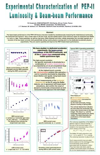
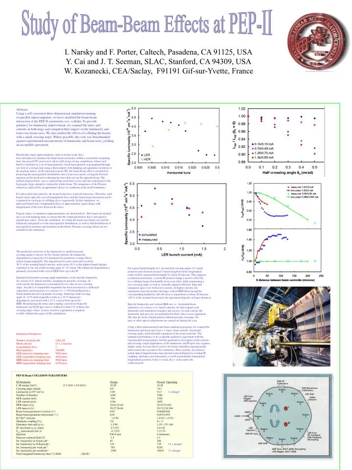
Study of Beam-Beam Effects at PEP-II • Narsky and F. Porter, Caltech, Pasadena, CA 91125, USA • Y. Cai and J. T. Seeman, SLAC, Stanford, CA 94309, USA • W. Kozanecki, CEA/Saclay, F91191 Gif-sur-Yvette, France Abstract: Using a self-consistent three-dimensional simulation running on parallel supercomputers, we have modeled the beam-beam interaction at the PEP-II asymmetric e+e- collider. To provide guidance for luminosity improvement, we scanned the tunes and currents in both rings and computed their impact on the luminosity and transverse beam sizes. We also studied the effects of colliding the beams with a small crossing angle. Where possible, the code was benchmarked against experimental measurements of luminosity and beam sizes, yielding an acceptable agreement. Historically, many approximations, such as strong-weak, have been introduced to simulate the beam-beam interaction within a reasonable computing time. Increased CPU power now allows full strong-strong simulations, where each bunch is modeled as a set of macroparticles. Each macroparticle is propagated through one turn of a storage ring using a linear matrix with damping and quantum excitations to the machine lattice. At the interaction point (IP), the beam-beam effect is modeled by projecting the macroparticle distribution onto a transverse mesh, solving the Poisson equation on the mesh and evaluating the force that acts on the opposite beam. The method deployed here uses a reduced fine mesh that covers only the central part of the beam pipe, large enough to contain the whole beam. The uniqueness of the Poisson solution is enforced by an appropriate choice of conditions at the mesh boundaries. For ultra-relativistic particles, the beam-beam force is purely transverse. Therefore, each bunch can be split into several longitudinal slices and the beam-beam interaction can be computed for each pair of colliding slices sequentially. In this simulation, we split each bunch into 5 longitudinal slices of approximately equal charge with interpolation of the force between the slices. Typical values of simulation input parameters are shown below. The beams are tracked up to several damping times to ensure that the output parameters have converged to equilibrium values. From the simulation, we obtain the transverse bunch size and the luminosity integrated over the macroparticle distribution, as well as full distributions of macroparticle positions and momenta in the bunch. Parasitic-crossing effects are not included in the simulation. The predicted sensitivity of the luminosity to small horizontal crossing angles is shown. At low bunch currents, the luminosity degradation is expected to be dominated by geometric overlap effects, which remain negligible. The degradation becomes noticeable at about 50 % of the nominal bunch currents, and reaches 10 % at the highest bunch charges simulated so far, for a half-crossing angle of ~0.5 mrad. The luminosity degradation is primarily associated with vertical HEB blow-up at the IP . Simulated horizontal crossing-angle dependence of the specific luminosity, for various e+/e- bunch currents, assuming no parasitic crossings. At each current, the luminosity is normalized to its value at zero crossing angle. An effect of comparable magnitude has been measured in a dedicated experiment, performed at e+/e-currents of ~1.35/0.85mA/bunch in a bunch pattern devoid of parasitic crossings. Inducing a half crossing angle of ~0.35 mrad originally results in a 15 % luminosity degradation, associated with a 25 % vertical blow-up in the HER. Reoptimizing the tunes and coupling corrections brings the luminosity and SLM spot sizes to within less than 5 % of their zero crossing-angle values. A more sensitive experiment is required to fully validate this aspect of the simulations. For typical bunch lengths of 1 cm and half-crossing angles of 1 mrad, positrons and electrons located 1 bunch length from the longitudinal center will be separated horizontally by about 20 microns. This suggests a related measurement: a closed IP-position bump is used to offset the two colliding beams horizontally from each other, while maintaining a zero crossing-angle as well as vertically aligned collisions. Data and simulation agree very well at low current. At higher currents, the simulation correctly predicts the large vertical HEB blow-up and the corresponding luminosity fall-off out to x-separations of about 20 microns (20 % of the nominal beam size); the agreement degrades at larger distances. Specific luminosity and vertical HEB size vs. horizontal beam separation, for various e+/e- bunch currents, for data (squares and diamonds) and simulation (triangles and circles). At each current, the luminosity and spot size are normalized to their value at zero separation. The data are from a bunch pattern without parasitic crossings. No tune or other optical adjustments are carried out during the scan. Using a three-dimensional beam-beam simulation program, we scanned the luminosity and beam spot sizes vs. tunes, beam currents, horizontal crossing angle, and horizontal separation of the beam centroids. The simulated performance is in acceptable qualitative agreement with the experimental measurements, but the quantitative description of the current- and crossing--angle-dependence of the luminosity and IP spot sizes requires further study. Several effects need to be better controlled experimentally, and/or taken into account in the simulation. These include, for instance, actual optical imperfections (uncorrected vertical dispersion, residual IP coupling, and lattice non-linearities), as well as potentially mismatched longitudinal positions of the e+ waist, the e- waist and/or the collision point. Simulation Parameters: Number of mesh cells 128x128 Mesh cell size 15 x 2 microns Longitudinal slices 5 Macroparticles 160,000 LER transverse damping time 9990 turns LER longitudinal damping time 4850 turns HER transverse damping time 5010 turns HER longitudinal damping time 2570 turns PEP-II Beam COLLISION PARAMETERS IR ParameterDesignPresentOperating C-M energy (GeV) (3.1 GeV x 9.0 GeV) 10.28 10.28 Crossing angle (mrad) 0.0 <0.1 Luminosity (x1033/cm2/s) 3.00 9.21 3 x design! Number of bunches 1658 1586 HER current (mA) 750 1550 LER current (mA) 2146 2450 HER tunes (x/y) 24.62/23.64 24.52/23.622 LER tunes (x/y) 38.57/36.64 38.512/36.564 Beam-beam parameter (vertical +/-) 0.03 0.064/0.046 Beam-beam parameter (horizontal +/-) 0.03 0.053/0.055 by*/bx* (cm/cm) 1.5/50. 1.4/32+,1.3/32- Optimum coupling (%) 3.0 4+, 2- Emittance (nm-rad) (y/x) 1.5/49. 1.35+-/35+,60- IP rms beam sy/sx (mm) 4.7/157. 5.4/141 Sx,y (microns)(at low I) 6.7/222 7.2/170 Injection Fill-Coast Continuous Detector solenoid field (T) 1.5 1.5 Int. luminosity in 8 hours pb-1 45 246 Int. luminosity in 24 hours pb-1 135 710 5.5 x design! Int. luminosity per week pb-1 785 4258 Int. luminosity per month pb-1 3300 16019 5 x design! Total integrated luminosity thru 7/1/2004 ~240 fb-1