Download

1 / 36
390 likes | 653 Vues
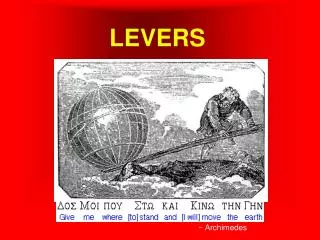
Levers&Pulleys. Parts of a Lever. Effort. Load. Load Arm. Fulcrum.

E N D
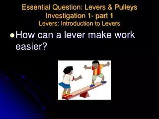
Parts of a Lever Effort Load Load Arm Fulcrum A lever is a simple machine used to reduce the amount of effort it would take to lift a load or reduce the amount of effort needed to do work.There are 3 types of levers: Class 1, Class 2, and Class 3. The effort needed to lift a load is measured in Newtons.
Class 1 Levers F A Class 1 Lever has its fulcrum between the effort and the load.
Class 2 Levers L A Class 2 Lever has its load between the effort and the fulcrum.
Class 3 Levers E A Class 3 Lever has the effort between the load and the fulcrum.
Levers QuizUse the following slides to quiz yourself on how how well you can match commonly used items with their correct class of lever.
Click on the correct Lever classification for the tool pictured below. Class 1 Class 2 Class3
Click on the correct Lever classification for the tool pictured below. Class 1 Class 2 Class3
Click on the correct Lever classification for the tool pictured below. Class 1 Class 2 Class 3
Click on the correct Lever classification for the tool pictured below. Class 1 Class 2 Class 3
Click on the correct Lever classification for the tool pictured below. Class 1 Class 2 Class 3
Class 1 Class 2 Class 3
Click on the correct Lever classification for the tool pictured below. Class 1 Class 2 Class 3
Click on the correct Lever classification for the tool pictured below. Class 1 Class 2 Class 3
Click on the correct Lever classification for the tool pictured below. Class 1 Class 2 Class 3
Click on the correct Lever classification for the tool pictured below. Class 1 Class 2 Class 3
Click on the correct Lever classification for the tool pictured below. Class 1 Class 2 Class 3
Click on the correct Lever classification for the tool pictured below. Class 1 Class 2 Class 3
Click on the correct Lever classification for the tool pictured below. Class 1 Class 2 Class 3
Click on the correct Lever classification for the tool pictured below. Class 1 Class 2 Class 3
Congratulations! You have successfully matched the common hand tools with their correct classification of lever. Be sure to remember: F L E 1 2 3
Levers and Advantage
Levers can provide Mechanical Advantage by reducing the effort needed to lift a load. The closer the fulcrum is to the load, the less effort is needed to lift the load. The load does not move a great distance. L E F
Levers can be used to move loads farther if the fulcrum is placed close to the effort. In this situation more effort is needed to lift the load, but the load will move farther than if the fulcrum was closer to the load. L E F
Single Fixed Pulley This pulley provides the user Directional Advantage, allowing someone to pull down to lift the load up. Is Mechanical Advantageprovided with this system? No, the effort needed to lift this load is equal to the weight of the load. This is because the load is supported by only 1 rope arm. You must also pull an amount of rope equal to the height you wish to lift the load
Single Moveable Pulley This pulley system provides Mechanical Advantage, requiring only ½ the effort needed to lift the weight of the load. If the load weighs 20 lbs, only 10 lbs of effort is needed to lift it. Can you tell why? The load is supported by 2 rope arms under the pulley. Each load arm supports half the weight of the load, so the arm pulling up uses only 10 lbs of effort to lift this load. You must pull twice as much rope as desired to lift the load a certain height. Example: Pull 2 ft of rope for each 1 foot of height that you want to lift the load.
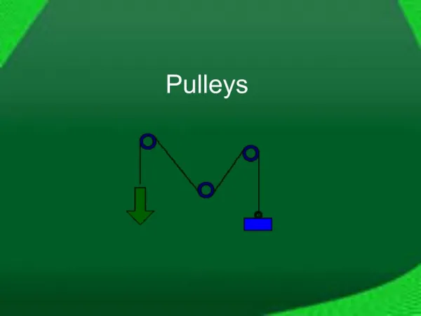
Single Fixed/Single Moveable Pulley This pulley system combines the properties of their single components into a system that provides both Mechanical and Directional Advantage.Do you see how this happens? How much rope must you pull? This pulley provides Directional Advantage by allowing the user to pull down to lift the load. It also provides Mechanical Advantage by using 2 rope arms to support the load, reducing the effort needed to lift the load by ½.In this system you pull 2 times as much rope for every unit of height that you want to lift the load.
Pulley Power! Single-Fixed Pulleys provide or Directional Advantage. You can make use of Counter-Weights in order to reduce your effort needed to lift the load. However, your effortPLUS the the counter-weight together must be equal to or be more than the weight of the load being lifted. Single-Moveable Pulleys provide Mechanical Advantage. You must pull 2 times the distance in rope that you wish to lift the load because the load is supported by 2 rope arms. You gain a Mechanical Advantage of 2 because you are using only ½ as much effort to lift the load. Combining Single-Fixed and Single-Moveable into Compound Pulley Systems allows the user to gain both Mechanical and Directional Advantage. The more rope arms supporting the load the greater the Mechanical Advantage.
An Inclined Plane is a simple machine that helps reduce the effort needed to move a load. Instead of picking up this load and lifting it straight upwards, the load can be pushed along an elevated plane. The user must move the load a greater distance, but the effort needed to move it will be less.
Screw Inclined Plane Wrapped around post = Screw A Screw is really an Inclined Plane wrapped around a center post.
Wedge edge Two Inclined Planes meeting together to create a sharp edge creates a Wedge.
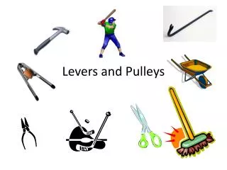
Wedges can be put to use in a variety of ways. The tips of screws, nails, and needles are wedges. Axes, splitting mauls, and picks have wedge edges. Scissors blades, pruning shears, and hand-held grass clippers all have wedge shaped blades. Planers have wedge shaped shapes for shaving wood particles. You will find many more examples if you take a closer look at many of the common tools used around your own house. Wedges are just one form of Simple Machine that helps us do work more easily.
Simple Machines allow users to more easily accomplish work. This PowerPoint presentation is a tool that you can use to review these concepts and prepare for the upcoming FOSS Assessment for theLevers and Pulleys module.