Download
1 / 53
530 likes | 677 Vues
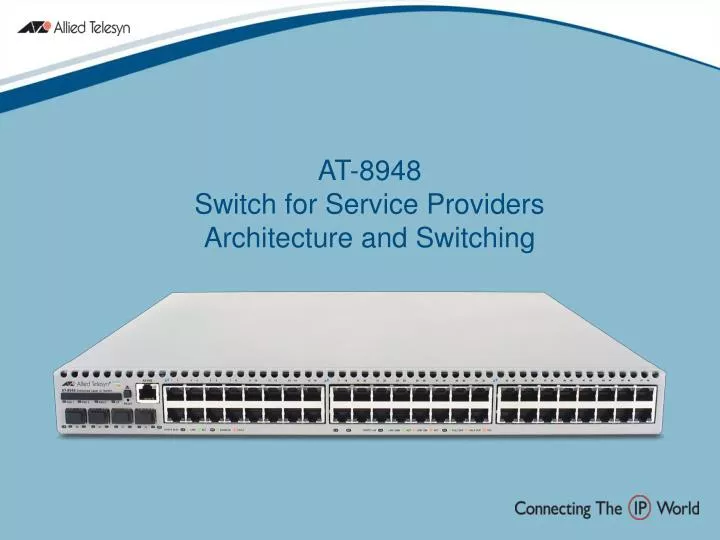
AT-8948 Switch for Service Providers Architecture and Switching. Introduction. This presentation covers the following topics: Switch architecture Power supplies Front-to-back cooling Switching tables and traffic flow Switching features CompactFlash. Switch Architecture.

E N D
AT-8948 Switch for Service ProvidersArchitecture and Switching
Introduction This presentation covers the following topics: • Switch architecture • Power supplies • Front-to-back cooling • Switching tables and traffic flow • Switching features • CompactFlash
Switch Architecture Front to back cooling Console port RJ45 Compact Flash slot 1RU 4 x GbE SFP ports 48 x 10/100Base-T RJ45
Switch Architecture PHYs PAC interface Switch Chip Marvel Prestera EX115 (37.6Gbps 13Mpps) CPU – 400Mhz DRAM – 128MB(up to 256 or 512MB) IPv6 Accelerator Interface (10Gbps) 32MB Packet Buffer Memory 32MB Flash Dual Hot Swappable PSUs
Power Supply Units - Overview Power supply design characteristics include: • A choice of AC or DC input PSUs • Redundancy, load sharing, and hot swappability • Performance monitoring
Devices – what can be mounted in the PSU bays? There are three devices that may be fitted into the PSU bays: • AC power supply • DC power supply • Fan only module (FOM) It’s important that both PSU bays are occupied to assist with internal cooling. If only one PSU is fitted, a FOM must be fitted in the other bay. FOM
AC Power Supply Features • 100-240v AC auto-ranging input voltage • High efficiency (>80%) • Class A EMC • Power factor correction • Current overload protection • Protection from current spikes • Over temperature alarm & shutdown • Command-line access for testing PSU operation
DC Power Supply Features • 48v DC input – compatible with -48v power distributiuon bus design • High efficiency (>80%) • Class A EMC • Current overload protection • Inrush current limiting • Protection from current spikes • Over temperature alarm & shutdown • Command-line access for testing PSU operation
FOM – Fan Only Module • The FOM has two cooling fans and is powered via a back-feed from the PSU fitted in the other bay
Power Supply Redundancy, Load Sharing and Hot-Swappability One PSU is adequate to supply the switch’s power. • If two are fitted they: • will load share • can be hot-swapped • If a PSU’s ‘power good’ LED is lit, it is supplying current to the unit
What is the command to check load-sharing performance? Release 2.6.2 includes the command: • ACTIVATE SYSTEM PSU=[BAY1|BAY2|ALL] TEST=[LOADSHARE] • This allows the switch to check if each PSU can supply the full load • Ensures that the remaining PSU will cope with the extra demand when the other PSU is removed
Can you remove and replace PSUs while the switch is operating? Yes, PSUs are hot-swappable • To meet regulatory requirements, two warnings are printed on the PSUs: • Caution: Disconnect power cord prior to removal of PSU • Caution: Disconnect all power cords to disable system power
Command-Line PSU Information • Some information is available via the command line interface: • SHOW SYSTEM • This command displays the module type, revision and serial number of each PSU or FOM that is installed, and the current condition of the modules
Example output from SHOW SYSTEMcommand with PSU information highlighted
Front-to-Back Cooling • The AT-8948 uses a linear airflow arrangement, which is designed to reduce the amount of warm air being re-circulated • Air is drawn in from the front and expelled from the rear, due to the action of the PSU and FOM fans
The Benefits of Front-to-Back Cooling • No need for ventilation clearances above, below, left or right of the switch • Cabling clearances at front and rear of the switch are adequate for ventilation • Ambient operating temperature range is 0 to 50C
Switching Tables • The switch makes its forwarding decisions based on the entries in its switching tables • There are 18 hardware and 8 software tables • Some statistics: • 4K IP interfaces • 4K entries in the Multicast table • 16K entries in the MAC table • 256K entries in the IP route table
Trunking • Trunking allows a number of ports to be configured to join together to make a single logical connection of higher bandwidth • While the trunk group is logically a single connection, physically it involves up to four separate links
Trunking • Hashing of information in the L2, 3,and 4 packet headers divides traffic between the ports in the trunk group
When configuring trunking be aware that: • A maximum of 7 groups may be created • A trunk group may include a maximum of 4 ports • Ports in a trunk group need not be contiguous • Ports in a trunk group must belong to the same VLAN and have the same tagging status
When configuring trunking be aware that (continued) • All ports in a trunk group must be added to VLANs together, and can only be removed from a VLAN as a group • If the tagging status of the ports in a trunk group is changed, it must be changed for all ports in the trunk group at the same time
When configuring trunking be aware that (continued) • Ports in a trunk group are set to autonegotiate at the trunk speed at full duplex • When a port is added to a trunk group, the speed setting for the group overrides the speed setting previously configured for the port
When configuring trunking be aware that (continued) • When a port is removed from a trunk group, the port returns to its previously configured speed and duplex mode settings • A trunk group may not include both 10/100 Ethernet ports and Gigabit Ethernet ports
When configuring trunking be aware that (continued) • A trunk group may not include a mirror port • The port trunking algorithm used on the AT-8948 may be compatible with that used on third-party devices
VLAN Double Tagging Available in 2.6.2 • An enterprise with multiple VLANs across multiple sites in a metropolitan area can use a public MAN to carry VLAN-tagged traffic between its sites • The public MAN carries traffic for multiple customers, so each frame must carry ‘customer-ID’ information • A second VLAN tag is inserted into each frame as it enters the public network and is removed on egress
Customer A Site 2 VLANs 1,2,3 Customer A Site 1 VLANs 1,2,3 AT-8948 AT-8948 Metro Ethernet network Customer B Site 2 VLANs 1,2,3 Customer B Site 1 VLANs 1,2,3 AT-8948 Customer A Site 3 VLANs 1,2,3 Customer B Site 3 VLANs 1,2,3 SwiA_DoubleTag VLAN Double Tagging
VLAN Double Tagging • ‘Familiar’ VLAN tagging: a 4-byte field is inserted into Ethernet frames
VLAN Double Tagging • When a frame enters the public MAN, a second, ‘per-customer’ VLAN tag is inserted
Configuring VLAN double-tagging Create the nested VLAN, specifying the customer-ID • CREATE VLAN={vlan-name VID=2..4094} NESTED
Configuring VLAN double-tagging Two types of ports are defined: • Customer ports connected to customers’ LANs: • ADD VLAN={vlan-name|2..4094} PORT=port-list NESTEDTYPE=CUSTOMER • Core ports connected to the public MAN • ADD VLAN={vlan-name|2..4094} PORT=port-list NESTEDTYPE=CORE
Configuring VLAN double-tagging To operate with other vendors’ equipment, it may be necessary to change the ‘Ethertype’ value in the customer-ID tag from its default value of 0x8100: • SET SWI NESTEDTPID=TagNumber
VLAN Double Tagging • Customer-ID tag
Private VLANs Available in 2.6.2 A Private VLAN is a VLAN which contains a specified group of ports that are prevented from communicating with each other at Layer 2. (Also known as a protected or port-protected VLAN)
Private VLANs • A typical application is in hotel installations where each room is serviced by one 10/100 Ethernet port, through which the hotel guest is able to access the Internet. In this situation it is undesirable to allow communication between rooms.
Private VLANs One customer is not able to snoop on the traffic from any other, yet each customer is able to access another network (usually the Internet).
Private VLANs • Ports that are members of a Private VLAN have one of two states, either 'private' (protected) or 'uplink' • Private ports cannot talk to other private ports but can talk to uplink ports. Uplink ports can talk to both private and other uplink ports, if they exist
Private VLANs • All traffic received on any private port in a Private VLAN is sent to the predefined uplink port, and only that uplink port, regardless of VLAN ID or MAC Destination address • Layer 2 traffic between private ports that are members of a Private VLAN is blocked
Configuring Private VLANs • Create a private VLAN using the command: • CREATE VLAN=vlan-name VID=2..4094 PRIVATE • Add the private ports to the VLAN: • ADD VLAN={vlan-name VID=2..4094} PORT=port-list • Add the uplink port(s) to the VLAN: • ADD VLAN={vlan-name VID=2..4094} PORT=port-list UPLINK If the uplink ‘port’ is a trunk group, the trunk group must be created before the ports are added to the private VLAN
CompactFlash CompactFlash is: • A small removable mass storage device that uses FLASH memory • Memory that doesn’t require power from a battery to retain stored data • Used to expand the amount of FLASH memory available to store files on the switch
CompactFlash • Two CompactFlash cards have been approved for the AT-8948: • AT-CF032A-n 32MB CompactFlash card • AT-CF0128A-n 128MB CompactFlash card • Where n is the number of cards in a package • (The size of the release file 89-261.rez is in the order of 6MB)
QoS Feature • Eight priority/egress queues per port Benefits • Allows traffic to be processed with up to eight levels of priority • Gives greater control to the network administrator • Increases differentiation of critical and non-critical network applications • Ensures availability of business-critical applications and services Catalyst 3550/3750 Metro • 4 egress queues per port
QoS Features • Bandwidth limiting down to 3Kbps, with burst limits • Bandwidth limit resolution down to 1Kbps Benefits • Very precise control of bandwidth guarantees • Burst limits improve bandwidth limiting of TCP sessions (avoids bandwidth flapping) Catalyst 3750 Metro • rate limiting at 8 Kbps increments “The bandwidth limiting capabilities of the 8948 are frightening!” – Senior Test Engineer, 8948 Development Team, ATR.
QoS Feature • 2 rates & 3 colours of bandwidth conformance Benefits • Allows SPs to offer differentiated services based on SLA • Customers exceeding their guaranteed SLA bandwidth can be given lower priority using re-marking • Non-conforming traffic can be identified through the entire network Catalyst 3750 Metro • 2 rate 3 colour (CIR/EIR) rate limiting
Traffic Class Bandwidth MAXBANDWIDTH MINBANDWIDTH Time QoS – Rate Metering Immediate Discard on Ingress RED Discard Re-mark Bandwidth Class 3 Excess Burst Size (EBS) MAXBURSTSIZE Excess Information Rate (EIR) Bandwidth Class 2 Re-mark Committed Burst Size (CBS) MINBURSTSIZE Committed Information Rate (CIR) Re-mark Bandwidth Class 1 Re-marking options : bandwidth class DSCP Egress Queue VLAN Tag User Priority
IPv6 – Why? • Increased address space • IPv4: 32 bit address gives 4 billion addresses • IPv6: 128 bit address gives 340 billion billion billion billion addresses!!!! • True end-to-end networking – Removes need for NAT • Some countries in Asia, with only a small IPv4 address allocation, have NAT up to 6 layers deep! • Some countries are running out of addresses now! • Increased security • Better QoS – Flow labels • Automatic configuration FE80:0000:0000:0000:0202:B3FF:FE1E:8329
IPv6 Feature • Dual IPv4 and IPv6 stack Benefits • IPv6 routing in software as part of feature set – DHCPv6, RIPng, multicasting • Ideal for early adopters looking for IPv6 compatibility now • Universities • Government/Military • Allows IPv4 and IPv6 to coexist in the same networks, easing transition to IPv6
IPv6 Feature • IPv6 accelerator card ACC-01 Benefits • Ideal for customers who demand IPv6 compatibility and high performance IPv6 routing • Provides wire speed hardware routing for IPv6 packets • Provides wire speed QoS – prioritisation and rate limiting • Accelerates tunnelling • Can sell as upgrade option for AT-8948A customers wanting future IPv6 capability • Future proofed • Start with IPv4 box • Sell IPv6 upgrade later