Download
1 / 40
400 likes | 662 Vues
WP 2: Dosimetry. WP2.4. development of simulation environment. simulation of patient dose with mathematical models. Overview. Scheme Consortium meeting 2009. WP2.5. WP2.3. WP2.2. development of methodology/ initial measurements. development of methodology/ initial measurements.

E N D
WP2.4 development of simulation environment simulation of patient dose with mathematical models Overview Scheme Consortium meeting 2009 WP2.5 WP2.3 WP2.2 development of methodology/ initial measurements development of methodology/ initial measurements development of methodology/ initial measurements WP2.1 decision on equipment and methodology PROTOCOL PROTOCOL PROTOCOL design of standard phantom development of standard dose indices measurement of dose in phantom for range of CBCTs in vivo TLD skin dose measurements scatter dose measurements measurement of indices on range of CBCTs Leuven, Manchester, involvement of Malmö and Leeds for standard dose index and phantom Leuven, Manchester, Athens, Malmö Leuven, Manchester, Athens, Vilnius Manchester, Athens
WP2.4 development of simulation environment simulation of patient dose with mathematical models Overview Current scheme WP2.5 WP2.3 WP2.2 development of methodology/ initial measurements development of methodology/ initial measurements development of methodology/ initial measurements WP2.1 decision on equipment and methodology PROTOCOL PROTOCOL PROTOCOL development of standard dose indices (M2.1) design of standard phantom measurement of dose in phantom for range of CBCTs (M2.2) in vivo TLD skin dose measurements (M2.3) scatter dose measurements VALIDATION OF INDICES M2.4 measurement of indices on range of CBCTs M2.5 M2.6 Leuven, Manchester, involvement of Malmö and Leeds for standard dose index and phantom Leuven, Manchester, Athens, Malmö Leuven, Manchester, Athens, Vilnius Manchester, Athens
Overview M2.1 Definition of standard dose index M2.2 Conclusion on dose distribution in anatomical phantoms M2.3 Results of in vivo measurements M2.5 Mathematical models developed and confirmed M2.6 Determination of effective dose and conversion factors for representative operating conditions and CBCT equipment T0 35 17 23 26 29 M2.4 Completion of scatter dose measurements and recommendations for protection of personnel
WP2.1 Standardised dose index for CBCTKU LeuvenUniversity of ManchesterLeeds Test Objects Malmö University
2.1 Dose index • Design and fabrication of PMMA dosimetry phantom (UNIMAN, LTO) • Discussion technical/risk-related index • Measurements: in PMMA phantom (UNIMAN) - TLD - Film in water phantom (KUL) - TLD (grid) - pencil ion chamber in anthropomorphic phantom (WP 2.2) (KUL+UNIMAN) • Dose index definition(Milestone 2.1, Month 18,finaldeliverable report Month 21)
2.1 Dose index • Film measurements: • Resolution ↑↑ • Calibrationforquantitativeresults?
FOV at the central axis Measuring points FOV off central axis Phantom 2.1 Dose index 3 indices defined 1 Phantom FOV axis 2 Measuring points Phantom
2.1 Dose index 3 indices defined Dose-area product (DAP) 3
2.1 Dose index 1 Validation in practice? CRUCIAL (change of DoW) 2 • Design of validationphantom (basedon PMMAdosimetryphantom, canaccomodate ion chamber,TLD and film) • Evaluation of the 3 dose indices withthisphantom • Decisiononstandardphantom 3
WP2.2 Anatomical phantoms: effective doseKU LeuvenUniversity of Manchester
2.2 Anatom. phantom ADULT PHANTOM PAEDIATRIC PHANTOMS
2.2 Anatom. phantom • Largenumber of effectivedosemeasurementsobtained(Milestone 2.2, Month 18) • ADULT PHANTOM • -15 different CBCT devices • Accuitomo 170 Galileos I-CAT Classic I-CAT NextGenerationIluma Kodak 9000 • Kodak 9500 NewTom VG NewTomVGi • PaxUni 3D Picasso Trio ProMax 3D • Scanora 3D SkyviewVeraviewepocs 3D • - Multiple exposureprotocols / field positionings
2.2 Anatom. phantom Exposure settings PAEDIATRIC PHANTOMS
2.2 Anatom. phantom Imaging Protocols
2.2 Anatom. phantom 10 year old phantom Max: maxillofacial, Den: dental, Mand: Mandible, Max: Maxilla, Imp: maxillary impacted teeth, Acc: 3D Accuitomo 170, HR: high resolution, Default: default machine’s settings, LR: left & right
2.2 Anatom. phantom Adolescent phantom Max: maxillofacial, Den: dental, Mand: Mandible, Max: Maxilla, Max Wisd: maxillary wisdom, Acc: 3D Accuitomo 170, Default: default machine’s settings
2.2 Anatom. phantom Effective doses • 10 year old effective dose • Average = 40μSv, minimum = 5μSv, maximum=99 μSv • Adolescent Phantom • Average=29μSv, minimum=3.5μSv, maximum=62 μSv • % radiation-induced fatal cancer risk to children: • 10 year old = 0.0004% and teenager = 0.00029% • Lower EDs for the Adolescent because of bigger size • Exception: Acc Molar + NewTom → Difference in mAs • Promax 3D: • Lowest → Small FOV, kV + mAs and 220o rotation • I -CAT 13cm + Acc 17x12 highest: • Full FOVs • Accuitomo: • Difference between 17x5 and 17x12 • 180o rotation reduces the dose by 50% and more
2.2 Anatom. phantom % contribution to effective dose • % organ contribution to effective dose • 10 year old phantom= similar contribution from RBM, thyroid, salivary glands • Adolescent phantom= higher contribution from salivary glands and thyroid because of size • Both phantoms • RBM contribution similar • RBM low doses but high radiosensitivity • Small contribution from skin and brain
2.2 Anatom. phantom • Currently • MeasurementscontinuedafterMilestone 2.2 • Multiple measurementsneededfor most devices, for correct assessment of effectivedose range • Adultphantomintercomparison • Paediatricphantoms Publications The current results are being compiled into two separate manuscripts: one containing adult measurements and another for the paediatric measurements.
WP2.3 In vivo dose measurements KU Leuven University of Manchester University of AthensVilnius University
2.3 In vivodose • TLD intercomparison: - compare TLD absorbed doses to ion chamberdose in two set- ups for Manchester, Leuven, Athens and Vilnius- anomalyfor Leuven solved • Measurementresults (Milestone 2.3 Month 24): >150 measurementsaccording to established protocol obtainedfrom different partners (KUL, VU, NKUA) • Currently:- gathering and analyzingresults- additionalmeasurementsforfilling in gaps (agegroup, indication,measurements at UNIMAN ifpossible (ethicalconstraints))
2.3 In vivodose Vilnius Number of patients until 2009/11/21 Diagnosis: Implant (both jaws) - IM Canine - CAN 38/48 - WT Orthodontic/surgery upper jaw – OS-U Orthodontic/surgery lower jaw –OS L Maxillary sinus- MS
WP2.4 Mathematical models for dental CBCTUniversity of Manchester
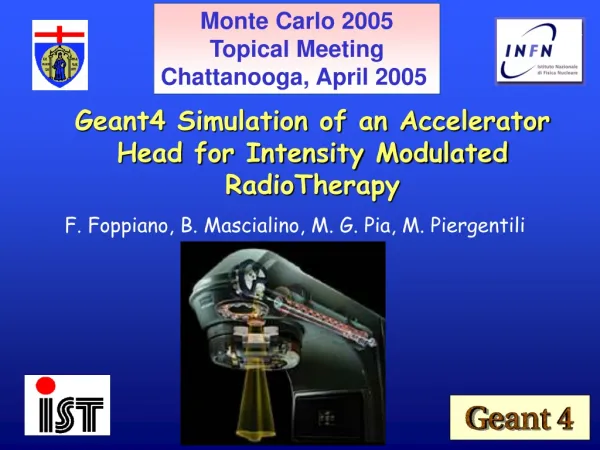
2.4 Math. models • Development of mathematical models for dental CBCT dosimetry: • factors to convert from measured standard dose indices and in-vivo skin dose measurement to effective dose • Calculation of conversion factors using Monte Carlo (MC) simulations (UNIMAN) • MC simulations are a class of computational algorithms that are based on repeated random sampling to compute the results • MCNP: a general purpose Monte Carlo N-Particle code • neutron, photon, electron or coupled neutron/photon/electron transport • tracks all particles at all energies that are necessary for these simulations • all interactions (cross-sections) between photons and matter are taken into account
2.4 Math. models Monte Carlo N-Particle code • Modelling the source • MCNP offers point, area, volume and multiple sources • Biasing direction & energy • Modelling the geometry • Planes, cylinders, spheres, cones and macrobodies like a box • Based on the above simple geometrical model you could build • Analytical phantoms • Voxel phantoms • Tallies = Output • Fluence, surface fluence, average fluence in a cell, energy fluence, energy deposition, pulse height • Input file describes: • Geometry in terms of cells and surfaces • Source • Materials • Particles involved • Tallies • MCNP5 installed on a cluster of 8 dedicated PCs and run under Linux operating system
2.4 Math. models Modelling the Source • Point source with forward biased direction • Biased direction: sends photons to the right direction • Source is a circular cone if the direction is biased • Set of 4 collimators, similar to X-ray tube, to shape the beam to a square (pyramidal) • MCNP5 does not offer moving sources • CT scanner is modelled with several point sources positioned on a “ring” • For a 360o rotation: 36 sources every 10 degrees • For a 180o rotation: 18 sources every 10 degrees
2.4 Math. models Modelling the Source, Collimators and Energy spectrum • Report 78 Spectrum Processor • 3D Accuitomo 170, 85kV and 90kV with 3.1mm Al filtration • Spectra normalised to area and used as input for MCNP5
2.4 Math. models Validation with a PMMA phantom • Cylinder of PMMA • 16cm diameter, 20cm height • Centre of the cylinder placed at the isocentre of the beam • 10x10 FOV
2.4 Math. models Validation with a PMMA phantom • Extensive tests were run to assess: • Point sources • Direction of particles for every point source • Position and size of collimators • Energy spectrum • Number of particles emitted from every source • Position and material of cylinder • Use of several tallies like fluence, surface, energy and cell fluence and energy deposition • Energy deposition (mGy/particle) calculated for a cell (2 x 2 x 2 cm3) in the middle of the cylinder • Energy deposited for two geometries: • Cylinder and cell made of air • Cylinder and cell made of PMMA • Ratio of the energy deposited for both geometries was calculated • For both energies % difference between simulated and experimental ratios was <14%
2.4 Math. models Future work • PMMA geometry • More energies • A range of positions in the cylinder • Axis and off-axis geometries • Range of field of views • Antropomorphic phantoms • Voxelise the two paediatric + ART phantoms • Validation on the 3D Accuitomo 170 Validation on other CBCT units • Use of other available voxel phantoms and compare with ATOM phantoms • List of conversion factors for a range of geometries and dental CBCT units
WP2.5: Measurements of scatter dose and radiation protection of personnel and helpersUniversity of ManchesterAthens UniversityVilnius UniversityKU Leuven
2.5 Scatterdose Protocol • Active measurements • Using ionisation chamber or dose rate meter • On standard measurement grid • Passive dosimetry • High sensitivity TLD badges • In rooms where CBCT is sole xray source
Are/Will be carried out on: Kodak 9000 Vatech Picasso Trio Vatech Pax Uni 3D Myray Skyview NewTom VGi NewTom 9000 NewTom VG Morita 3D Accuitomo Morita Veraviewepocs 3D Planmeca ProMax 3D Soredex Scanora 3D Sirona Galileos In: UK Greece Belgium Lithuania 2.5 Scatterdose Scatter measurements
Variation in plane of isocentre Maximum scatter at 1 m 2.5 Scatterdose Examples of initial measurements
2010 SCHEDULE M2.4 Completion of scatter dose measurements and recommendations for protection of personnel M2.5 Mathematical models developed and confirmed M2.6 Determination of effective dose and conversion factors for representative operating conditions and CBCT equipment T0 35 17 23 26 29 WP2.1 Validatedose indices in plexiphantom, final design of standardphantom, start concludingmeasurements in standardphantom. WP2.2 Additionalmeasurementsdependingopportunities WP2.3 Additionalmeasurementsdependingonopportunities, measurements in Manchester ifethical issues are solved WP2.4 Continue and finish set-up and validation of MC framework, simulatedosedistributions, determineeffectivedose and calculateconversion factors (M2.5 and 2.6) WP2.5 Completion of scatter dose measurements around CBCTs and recommendations for protective measures and positioning of CBCT units in dental offices (M2.4)
Change of DoW 3 1 2 • Dose index validation in practice?CRUCIAL • - definition has not been straightforward (variety of scanners and parameters) • large impact (objectiveway of comparing doses of CBCTs, impact on vendor data, decisions in acquisitionprocess, tasks of medicalphysicists • Simulationworkwithradiotherapy planning system:less relevant • Back-up for MC calculationsbutlessadvanced and more experimental(kV beamsinstead of MV beams) • Muchexperimentalpreparatoryworkthatcannotbeusedforother WP2 objectives • Initialchoice: • versatile system forquickdosepredictionfor different geometries nowmanyexperimental data available in WP2.2 • simulation expertise at KUL now MC expertise in parallel project