Download
1 / 90
1.14k likes | 1.42k Vues
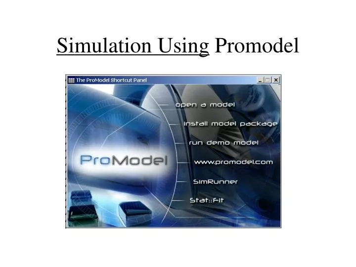
Simulation Using Promodel. System Definition. What is a system? ---- System is a collection of elements that functions together to achieve a desired goal A system consists of multiple elements Elements are interrelated & work in cooperation A system exists for achieving specific objectives.

E N D
System Definition • What is a system? ----System is a collection of elements that functions together to achieve a desired goal • A system consists of multiple elements • Elements are interrelated & work in cooperation • A system exists for achieving specific objectives
entity arrivals L E L L entity exits L EXIT SYSTEM to ProModel MODEL
ProModel Modeling Elements The main elements are: • LOCATIONS(object) • ENTITIES (object) • ARRIVALS (interaction) • PROCESSING (interaction) • RESOURCES entity arrivals L E L L entity exits L EXIT
ProModel™ - Sequence • It is usually easier if you draw a picture / flow chart / etc. • It is also usually easier to work backwards
ProModel™ - Sequence Once a clear picture of what is required is defined, then declare and define the following modules within ProModel: • Locations • Entities • Arrivals • Processing • Variables • …
ProModel™ - Locations • Locations represent fixed places in the system where entities are routed for processing,delay, storage, decision making, or some other activity. • some type of receiving locations to hold incoming entities. • processing locations where entities have value added to them.
ProModel™ - Locations Things to define in the Location module found under the “Build” tab: • Name • Capacity – How many entities at a time • Units – How many of this location type • DTs – Downtime logic (covered later) • Rules – Decision rules (FIFO, random, etc.) • Color, size, and layout placement can be done.
ProModel™ - Entities • Anything that a model can process is called an entity. Some examples are parts or widgets in a factory, patients in a hospital, customers in a bank or a grocery store,and travelers calling in for airline reservations. • The entities are often also limited in number, depending upon the program type, so creativity may again be required. • Entities are discrete units that can be bundled. This aspect is covered later.
ProModel™ - Entities Things to define in the “Entities” module under the “Build” tab: • Name • Speed of Travel (default is 150 fpm) • Color, size, etc. • Attributes are set by a separate module under “Build” and cover locations and entities. This is a future topic as well.
ProModel™ - Arrivals • The mechanism for defining how entities enter the system is calledarrivals. Entities can arrive singly or in batches. • Can be a single occurrence, infinite, or anything in between, as defined in the logic. • Each entity entering the system will have its own arrival protocol.
ProModel™ - Arrivals Things to define for “Arrivals” under the “Build” tab: • Entity Name • Location of arrival • Quantity at each arrival • First time of arrival (default is when the system FEL causes the arrival)
ProModel™ - Arrivals Things to define for “Arrivals” under the “Build” tab, continued: • Batch size: the number of entities arriving at a time (Qty each). • Frequency: the time between the arrivals of successive entities • Occurrences :the total number of batches of arrivals The batch size, time between successive arrivals, and total number of batches can be either constants or random (statistical distributions). • First Time:the first time that the arrival pattern is to begin is termed • Logic – Special conditions, etc.
ProModel™ - Processing This is where the meat of the program is defined. • Processing describes the operations that take place at a location • such as the amount of time an entity spends there, the resources it needs to complete processing,and anything else that happens at the location, including selecting an entity’s next destination.
ProModel™ - Processing Things to define for “Processing” under the “Build” tab: • Incoming Entity (one entry allowed) • Location – where the entity is NOW • Operation – What logical steps are to be applied to the entity at the location above. Can be waits, updates on tracking variables, costing, etc. • Output – Declare the SAME entity unless you are really intending to change entities in this step.
ProModel™ - Processing Things to define for “Processing” under the “Build” tab, continued: • Destination – The target location. Can be more than one, but each location is defined separately, using the return key. If more than one location is used as a target, you need rules for selection. • Rule – This section defines the logic for how and which location gets the entity, whether as a preloaded subroutine or a user-defined subroutine. • Move Logic – Used forResources, primarily.
ProModel™ - Variables • Variables are used for tracking system, location and entity performance. • Can be used for verification purposes. • Essentially there is no limit on the number of variables that can be issued.
INC/DEC statements INC variable ID, increment value DEC variable ID, decrement value default increment/decrement value is one. +, -, / , *, = Valid in any logic field (operation, move logic) VARIABLE (continued)
ProModel™ - Variables Things to define for “Variables” under the “Build” tab: • ID – Declares the variable name • Type – Integer or real, default is integer • Initial Value • Notes – Useful for large programs to track what this variable is supposed to do. • Icon – This tells you when a counter appears on the layout.
ProModel™ - other elements • More items available, and to be discussed later: • Resources – Forklifts and the like. • Path Networks – used to constrain movements within a shop model, for example. • Arrays, Macros, User Distributions, etc. help convert the process into a definable model. • Background Graphics can be used for labeling and identifying components in a layout.
ProModel™ - Distributions Distributions are declared in ProModel shorthand, thusly: • N(12,3) means a normal distribution with mean 12 and standard deviation of 3. • U(10,1) means a uniform distribution with a center of 10 and a half-width of 1 (ranges from 9 to 11). • T(1,2,3) means a triangular distribution with a minimum of 1, a mode of 2, and a maximum of 3. • E(5) means an exponential distribution with a mean time between events of 5.
ProModel™ - Distributions • All distribution types have theoretical expected values and variances • The expected values are to be used for model verification in comparison to the model-generated confidence intervals.
Limits of ProModel Student version • 20 Locations • 8 Entity Types • 8 Resource Types • 5 Attributes • 15 RTI parameters
Buiding your FirstModel Customers visit the neighborhood barbershop Fantastic Dan for a haircut. • The customer interarrival time is exponentially distributed with an average of 10 minutes. • Dan (the barber) takes anywhere from 8 to 10 minutes, uniformly distributed (mean and half-width of 9 and 1 minute respectively) for each haircut.This time also includes the initial greetings and the transaction of money at the end of the haircut. • Run the simulation model for one day (480 minutes). Find these answers:
Fantastic Dan Model a. About how many customers does Dan process per day? b. What is the average number of customers waiting to get a haircut? What is the maximum? c. What is the average time spent by a customer in the salon? d. What is the utilization of Barber Dan?
ProModel™ - Attributes • Two types: Entity and Location. Entity is more common. • Attributes can be examined and acted upon by the logic in any part of the program from arrivals to departures. • Some examples of attributes are part type, customer number, and time of arrival of an entity, as well as length, weight, volume, or some other characteristic of an entity. • Attributes of an entity are copied over whenever an entity is cloned. This happens when entities are split, for example.
ProModel™ - Attributes • Within ProModel, select the Attribute field from the drop-down Build menu. • The required elements are “name”, “type” (integer/real), and classification. • Values are assigned in the logic. • Attributes are especially useful when assigning a user condition for routing.
Using Attributes to Track Customer Types Problem Statement: Customers visit the neighborhood barbershop Fantastic Dan for a haircut.Among the customers there are 20 percent children, 50 percent women, and 30 percent men. The customer interarrival time is triangularly distributed with a minimum,mode, and maximum of seven, eight, and nine minutes respectively. The haircut time (in minutes) depends on the type of customer and is given in following Table.This time also includes the initial greetings and the transaction of money at the end of the haircut. Run the simulation model for one day (480 minutes).
Continued a. About how many customers of each type does Dan process per day? b. What is the average number of customers of each type waiting to get a haircut? What is the maximum? c. What is the average time spent by a customer of each type in the salon? What is the maximum?
Cycle Time • The Clock and Log are functions built into ProModel to allow us to keep track of system events such as cycle time, lead time, or flow time within the system. • The Clock function returns the current simulation clock time in hours, minutes, or seconds. • The value returned is real. • The Log function is used to subtract an expression from the current simulation. • clock time and stores the result with a text string header. Time_In = Clock() Log "Cycle Time =", Time_In
Decision Statements • In ProModel you can make use of several general control statements for decision making. ProModel meets the modern standards of structured program design. sequences, decisions, and loops: • Sequences: Program statements are executed one after another. • Decisions: One of two blocks of program code is executed based on a test for some condition. • Loops: One or more statements are executed repeatedly as long as a specified condition is true.
IF-THEN-ELSE Statement • An IF block allows a program to decide on a course of action based on whether a certain condition is true or false. • A program block of the form: IF condition THEN action1 ELSE action2
continued • WHILE-DO Loop The WHILE-DO block repeats a group of statements continuously while a condition remains true. If the condition is false, the loop is bypassed. • DO-WHILE Loop The DO-WHILE block repeats a group of statements continuously while a condition remains true. This loop will be executed at least once; use it for processes that will be executed at least once and possibly more. • GOTO Statement The GOTO block jumps to the statement identified by the designated label. A label should follow the normal rules for names. A colon follows a label.
ProModel™ - Arrival Cycles • Used to meter arrivals, such as when lot sizing is used • Used to create a variable arrival cycle. This can model the customer flow to more accurately reflect peak vs. slow periods.
ProModel™ - Arrival Cycles Build -> More Elements -> Arrival Cycles Fields: • ID – The user-defined name • Qty /% - Defines the basis for the total number of arrivals per cycle occurrence • Cumulative – Selects whether the cumulative format is used for the data table. • Table – Forwards the user to the edit field.
ProModel™ - Arrival Cycles Table Editing • Two fields: Time and Qty / %. The time field is always cumulative in terms of hours. • The arrivals are randomly spaced within the arrival band. • Once the table is defined, the next task is to summon it from the Arrivals menu.
ProModel™ - Arrival Cycles Arrivals Editing • The fields affected are the Qty each, Number of Occurrences and Frequency • Qty Each – Use the expression for the numerical quantity for the whole cycle, and select the cycle by name from the drop-down menu. • Number of Occurrences – Defines the number of cycles expected per simulation run • Frequency – Sets the time between the start of on cycle until the start of the next cycle. This must be longer than the cycle time or you will get a runtime error.
Multicapacity locations. • Locations are modeled as a single unit with multicapacity. • All elements of the location perform identical operations. • When one element of the location is unavailable due to downtime, all elements are unavailable. Only clock-based downtimes are allowed.
Multiunit Locations. • Locations are modeled as single capacity but multiple units. • These are locations consisting of two or more parallel and interchangeable processing units. • Each unit shares the same sources of input and the same destinations for output, but each may have independent operating characteristics. • This method provides more flexibility in the assignment of downtimes and in selecting an individual unit to process a particular entity.
Multiple, single-capacity locations • Locations are modeled as individual and single capacity. • Usually noninterchangeable locations are modeled as such. • By modeling as individual locations, we gain the flexibility of modeling separate downtimes for each element. • In addition, we now have complete flexibility to determine which element will process a particular entity.
L L L L L Multi-Unit / Multi-Capacity / Multiple Locations Single Unit Single Capacity Single Unit Multi-Capacity L L L L L Multi-Unit Single-Capacity L Multi-Unit Multi-Capacity L L L L
Move Logic Four choices of constructs are available in the Move Logic field: • MOVE—to move the entity to the end of a queue or conveyor. • MOVE FOR—to move the entity to the next location in a specific time. • MOVE ON—to move the entity to the next location using a specific path network. • MOVE WITH—to move the entity to the next location using a specific resource (forklift, crane).
Poly Furniture Factory • Wooden logs are received at the receiving dock of the Poly Furniture Factory at the rate of one every 10 minutes. • Logs go to the splitter, where four pieces are made from each log. The splitting time is Normal (4,1) minutes. • The individual pieces go to the lathe, where they are turned for another Triangular (3,6,9) minutes and made into rounds. • The rounds go on to a paint booth, where they are converted into painted logs. Painting takes Exponential (5) minutes. Painted logs go to the store. • Consider a material handling time of one minute between each process. Make a simulation model and run the simulation for 10 hours.
E L L L L EXIT ProModel™ - Resources A Resource is person, equipment item, or device that performs the following functions: • Entity transport • Assisting in operations (such as an inspection) • Location maintenance • Resource maintenance
ProModel™ - Resources • Resources can consist of one or more units with common characteristics, such as a group of forklifts. • Resources can be dynamic (requiring a path network) or static. Downtimes are also included as part of the model. • Resources have names and name-index numbers. Path networks also have names and nodes.
ProModel™ - Resources Static Resources • Will appear in only one location during the operation of the model, however, it can be used logically to move entities between locations. • There is no status light, but the resource will be green when in use and red when down (if no other graphics are used).
ProModel™ - Resources Dynamic Resources • Requires definition of the Path Network before creation, since it will be referenced in the Specifications dialog box. • The Specifications dialog box defines the rules by which the resource will operate. • Each Resource is defined using the Build -> Resources task sequence