Download
1 / 34
360 likes | 438 Vues
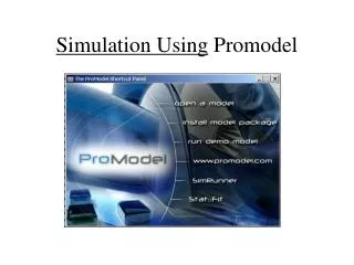
Building Simulation Models using ProModel. Please Read Practice Model Shop Floor found on the next page. Sequence. 1. General Info 2. Background 3. Locations 4. Entities 5. Path Networks 6. Resources 7. Processing 8. Arrivals. Success. Select “General Information” from

E N D
Building Simulation Models using ProModel
Please Read Practice Model Shop Floor found on the next page
Sequence 1. General Info 2. Background 3. Locations 4. Entities 5. Path Networks 6. Resources 7. Processing 8. Arrivals Success
Select “General Information” from the ProModel “Build” menu
You may give your model a Title, choose your time and distance units, write a note about the model, select which graphic library to use and complete initialization or termination logic
Background Graphic • Drawings, icons or imported • floor plans of a facility. • Go to Build - Background Graphics, • then Edit - Import Graphic to • import the background. • To place background icons on the • layout, click on the icon and then • click in the layout window.
Select in Front of or Behind the Grid Select Background Graphics
Imported graphic background
Enter Background Labels Etc.
Locations Physical location like a lathe Transparent location like a place on the floor
Locations • Locations may be visible or or transparent • Account for actual and “pass through” locations • Locations have capacity. Set it to control use and movement
Locations • Don’t collect statistics on locations that are not important • Don’t confuse the location “lathe” with the resource “lathe operator” • Establish work locations on machines but in front of counters, desks, etc.
Note capacity settings Click on the icon and then on the layout where you want the location placed
This is all one location To make more than one icon represent the same location, click off the “new” check box
Counter Gauge Conveyor or Queue Text Label Status Light Entity Spot Region
A Multi-unit location
Use the special conveyor location icon Start the conveyor with a left mouse click. End the conveyor with a right mouse click.
Right click on the conveyor to bring up editing options
The Edit Graphic brings up conveyor settings and the conveyor options window.
Locations Now, along with the instructor, enter the locations for the “Shop Floor” model
Entities • Objects that have actions performed on them • Make multiple graphics to show action or status Pallet of Boxes • Size graphics to match background • Graphic change is addressed in operation and/or move logic
Entities Now, along with the instructor, enter the entities for the “Shop Floor” model
Path Networks Node N2 Node N3 Node N1 Node N5 Resource Point at N1 Interface Joint Interface Path Segment
Path Networks • Networks consist of path segments, nodes and interfaces • Segments are measured for distance or time • Nodes should not be placed on top of locations (put them next to it) • Only one interface per location on the same network is allowed
Path Networks • Path segments can only join each other at nodes. • You must have a path network to use a dynamic resource • Plan path networks carefully to accurately portray the movement of resources and entities
Note Speed & Distance vs. Time Note measured distance
Click on the Graphic field to change the color of the path segments or to make the network invisible during the simulation
Interfaces show the relationship between path nodes and locations.
Nodes may be renamed in the Nodes module for ease of identification later.
Path Networks Now, along with the instructor, enter the Path Network for the “Shop Floor” model