Download
1 / 31
421 likes | 901 Vues
Simulation of Anechoic Chamber. C. Di Giulio LNGS Assergi (AQ). Chicago Sep. 2010. OUTLOOK. Introduction Shielding Absorber Material Theory Absorber Model First simulation test. Introduction to Anechoic ( “ No echo ” ) chambers.

E N D
Simulation of Anechoic Chamber C. Di Giulio LNGS Assergi (AQ) Chicago Sep. 2010
OUTLOOK • Introduction • Shielding • Absorber Material • Theory • Absorber Model • First simulation test
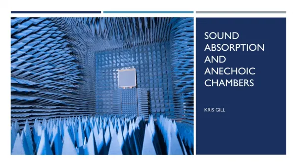
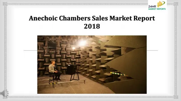
Introduction to Anechoic (“No echo”) chambers A radio frequency “anechoic chamber” is a shielded room whose walls have been covered with a material that scatters or absorbs so much of the incident energy that it can simulate free space.
Kinds of anechoic chambers • Compact Range Chamber • Tapered Anechoic Chamber • Near Field Test Chamber • Rectangular Chamber
Compact Range Chamber • This type of range makes use of optics principals and puts a source horn at the focal point of a reflector which results in plane waves coming from the reflector. This reduces the path length needed to create plane waves. • if the reflector was sufficiently large and if the edges around the reflector were terminated properly to limit diffraction interference, the resulting beam would be collimated and have minimal phase ripple across the test region. • the idea is to measure a large aperture antenna while minimizing the length of chamber needed.
Tapered Anechoic Chamber • The tapered chamber actually uses the reflections off the walls to its advantage. It was found that suppression of reflections for low frequency broad-beamed antennas was almost impossible. • Tapering one end of the chamber would cause the chamber to act like an indoor ground reflection range. The reflections off of the chamber walls actually add together to form an almost uniform plane wave at the test region. The shape of this chamber and the wave front emanating from it is reminiscent of horn antenna. • The cost of a tapered chamber is usually less than a rectangular chamber. • The tapered chambers are used mostly for low frequencies in the VHF(30-300 MHz) / UHF(300 MHz a 3 GHz) range.
Near Field test Chamber • The test antenna is measured in the near-field and a near-field to far-field transform is used to obtain the far-field pattern. • The disadvantage of this method is that points in different planes are needed to get an accurate far-field calculation. • Other disadvantage is that this method is very math intensive and requires more equipment to get a complete scan of the antenna.
Rectangular Chamber • Most common type of chamber because they are easy to build and easier to design than other types of chambers. • These chambers range in size depending on what the operating frequency is and also on what is being tested. The major specification is that the chamber must be long enough so that the antennas under test are in the far-field. • the chamber to be deep enough so that we don’t get a skipping affect of the electromagnetic wave off the floor of the chamber.
Shielding • To attenuate extraneous RF signals from interfering with the measurements (Faraday cage) • To prevent the signals generated inside the chamber from escaping • The thickness of the shielding material will dictate how much attenuation is achieved • The attenuation of the shielding can be degraded if the penetrations of the chamber are not handled with care (doors problem). • The most important thing is to make sure that all pieces of metal used for the enclosure have a good electrical connection. aluminum foil which has contact adhesive on one side and simply adhere it to the wall of the enclosure.
Absorber Material • absorber doped with carbon to achieve the dissipation of the electromagnetic wave. • coating a pyramidal shaped object with absorbing material lowered the level of reflected signals, this this is because the geometry results in multiple reflections in the direction of the apex of the pyramid . Family: • < 1GHz (ferrite tiles and hybrid absorbers) • >1GHz (Solid foam, pyramidal absorber )
Absorber f < 1GHz Ferrite Tile . Magnetic Losses Preferred technology for Low frequencies (up to 1GHz), it has low profile. It cannot be used for high frequencies
Absorber f > 1 GHz Wedge and pyramid Electric Losses A variant of pyramidal absorber wedge does not show backscattering. Preferred technology for QZ (Quite Zone) treatment and for RCS(Radar Cross Section) chambers.
Other absorber Flat laminate . Electric Losses Preferred technology for laboratory set ups. It is a sandwich of different foams with different amounts of carbon loading. About 20dB absorption as frequency increases. Hybrid Absorber . Electric and Magnetic Losses Preferred technology for EMC Applications. foam has to have special formula for good matching with ferrite tile at the bottom. At High frequencies its performance is not as good as MW pyramid of equal size. Flat top causes undesired reflections at MW range.
Theory: chamber dimension • The chamber must be long enough to be in the far-field of the antennas under test. if the antenna is large compared to the wavelength: D refers to the maximum physical dimension of the antenna. R refers to the distance away from the antenna. D Else:
Theory: chamber dimension • The chamber must also be deep enough so that the propagating wave does not skip off the sides of the chamber. • We need the incident angle to be shallow enough so that the propagating wave gets attenuated in the foam and doesn’t skip. This equation comes from the fact that the angle of incidence on the adjacent walls and ceiling should be less than 60 degrees. • Quiet Zone:is the area where the phase difference from the ensuing wave is kept to a minimum. In this area, all extraneous signals should be kept at a level of -40dB below the main beam
Theory: the specular regions • The regions on the side walls that will see the first off-axis wave or first reflection. The wave propagating from the source horn is going to be reflecting off the walls the whole way down the chamber. At each reflection, the wave gets attenuated more and more • look at zones of constant phase call Fresnel zones: This region is only used to guide the absorber layout design.
Pyramidal absorber theory This material is volumetrically loaded having the same constitutive parameters through the volume of the pyramid Popular types of absorber have constitutive parameters of: Non magnetic material Low permittivity with losses We will study how the electromagnetic wave behaves as is incident on to a wall of this type of absorber.
Pyramidal absorber theory At the tip of the absorber The wave impedance is that of air NO SUDDEN CHANGE IN WAVE IMPEDANCE = LOW REFLECTIVITY Along the length of the pyramid the wave impedance falls between those two values. At the base of the pyramid The wave impedance becomes
Pyramidal absorber theory Let’s approximate by saying that the pyramid is equivalent to a solid medium of 1/3 the height Let’s assume a length of 30cm The wavelength at 3GHz is 10cm And at 10GHz is 30mm For 3GHz Wavelength at 3GHz Approximate thickness of equivalent solid material
Pyramidal absorber theory Let’s approximate by saying that the pyramid is equivalent to a solid medium of 1/3 the height For 10GHz Wavelength at 3GHz Approximate thickness of equivalent solid material In practice the reflection coefficient may not be as small as this but it will be significantly Smaller than at 3GHz
Pyramidal absorber Models • MODELING OF RF ABSORBER FOR APPLICATION IN THE DESIGN OF ANECHOIC CHAMBER B.-K. Chung and H.-T. Chuah Plane-boundary lossy dielectric model for pyramidal absorber. The metal boundary may be modeled as a lossy dielectric with an effective dielectric constant, εeff , and an effective conductivity, σeff
AEP 12 Pyramidal absorber Models AEP 18
Pyramidal absorber Models AEP 18
Pyramidal absorber Models WORK IN PROGRESS… (help??)
Conclusion • A simple model for the anechoic chamber was presented. • A on more accurate model it’s on going…. • Commercial software like CST Microwave studio can help to do a best estimation of the attenuation in the anechoic chamber but … 36000 € :(