Download
1 / 23
230 likes | 381 Vues
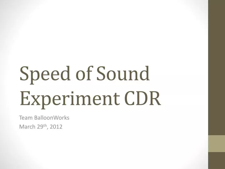
Speed of Sound Experiment CDR. Team BalloonWorks March 29 th , 2012. Table of Contents. Introduction Mission Goal Expected Outcomes Payload Design Electrical, Software, and Mechanical Design System Testing Pre Flight Checklist Data Analysis Plan Master Budget. Mission Goal.

E N D
Speed of Sound Experiment CDR Team BalloonWorks March 29th, 2012
Table of Contents • Introduction • Mission Goal • Expected Outcomes • Payload Design • Electrical, Software, and Mechanical Design • System Testing • Pre Flight Checklist • Data Analysis Plan • Master Budget
Mission Goal To measure the speed of sound in Earth’s atmosphere in order to establish a relationship between speed of sound and altitude up to 30,480 meters and to consider the effects of atmospheric properties on the speed of sound.
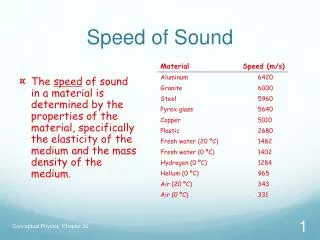
Expected Outcomes • Speed of sound is primarily dependent on temperature. • Speed of sound will decrease until the balloon reaches the tropopause. • Speed of sound remain constant in the tropopause. • Speed of sound will increase in the stratosphere. • Humidity is expected to play a minor role in determining the speed of sound when compared to temperature changes.
Principle of Operation • Ultrasonic transmitter will emit an ultrasonic pulse. • Receiver will detect the pulse after it travels through ambient air. • Test circuit will determine the time it takes for the pulse to travel the fixed distance between transmitter and receiver. • Payload will have both an experiment and circuitry chamber. • Experiment chamber will allow temperature inside to be equal to ambient temperature and will contain the transmitter and receiver. • Circuitry chamber will be closed to the environment and will hold the power supply, test circuit, and BalloonSat.
Initialize all hardware pins and declare all variables Software Design Initiate EEPROM address to 0 • Pre-Flight Program • Sets all hardware pins and variables • Sets EEPROM address • Sets RTC Set RTC to desired HH:MM:SS Display
Read the address from the EEPROM on the BASIC Stamp Is EEPOM ADDR>=max EEPROM Address Yes End Program No Write RTC data to EEPROM Get hour, minute, and second from RTC Start the counter to count until the arrival of the pulse Send a 40kHz pulse Get counter data Check comparator status Write address to the EEPROM on the BASIC Stamp Reset the counters Write counter data to EEPROM Pause in order to maintain consistent data acquisition of every fifteen seconds
Run the term232 program to save data into a file Post-Flight Program Is EEPOM ADDR>=max EEPROM Address Yes End Program No Retrieve the data for the EEPROM Display the data showing the address as well as the values Pause
Mechanical Design • Hexagonal Design • Extruded polystyrene rigid foam insulation material
Mechanical Design Units in mm
System Testing • Wind Test • Determine whether the mechanical design would effectively block the wind effects on speed of sound • Air Blower, Oscilloscope, Test Circuit, Prototype Box • Successful • Vacuum Test • Determine the maximum altitude the receiver can detect the ultrasonic pulse • Vacuum Chamber, Oscilloscope, Test Circuit • Successful to 29,410 m
System Testing • Temperature Test • Determine whether the experiment chamber maintains a thermal equilibrium with the surroundings. • Two HOBOS with temperature probes and prototype box • Successful • Electronics Test • Prove that the test circuit can store the counts to the EEPROM and that the post flight software can retrieve the counts. • Test Circuit, Pre/Flight/Post software, PC. • In progress
Pre Flight Checklist • Calibration: Sync RTC time with the LaACES GPS beacon time the morning of the launch.
Data Analysis Plan • Post Flight Software will retrieve the data stored during flight. • Excel will: • Convert the counts to decimal numbers. • Multiply by 1/f of the timing oscillator (10 MHz) to obtain the time the sound pulse took to get from the Tx to the Rx • Divide 0.19 m by the above time to get speed of sound. • Obtain temperature, pressure, and relative humidity data from Team Flyboys. • Obtain altitude vs. time data from LaACES. • Construct graphs of speed of sound vs. altitude. • Construct graph of measured speed of sound vs. theoretical speed of sound.