Download
1 / 39
520 likes | 841 Vues
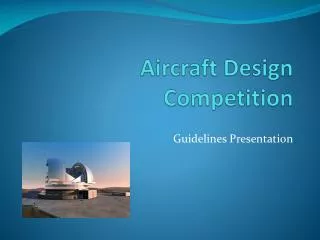
Aircraft Design - The Design Process. For more detailed notes please refer to www.rmcs.cranfield.ac.uk/aeroxtra. Recommended Further Reading. D.Howe – Aircraft Conceptual Design Synthesis D.Raymer – Aircraft Design, A Conceptual Approach J.Roskam – Airplane Design, Parts 1-8

E N D
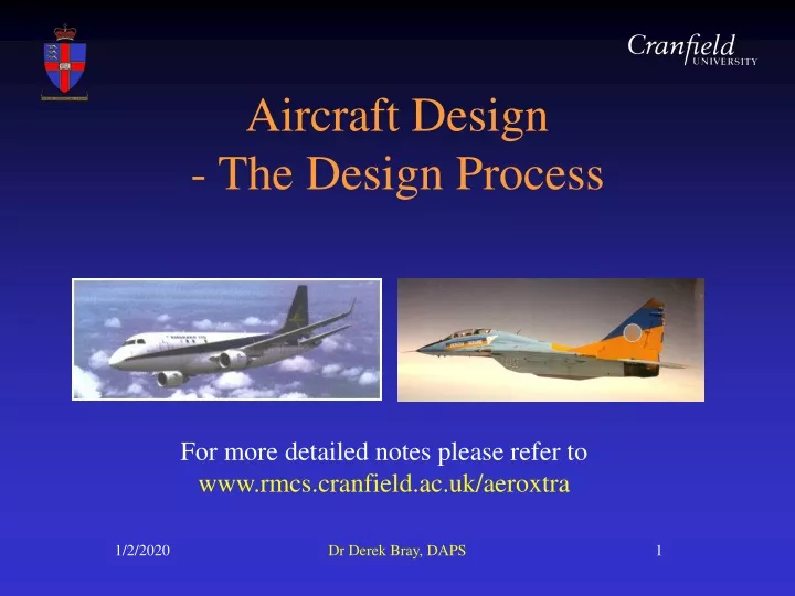
Aircraft Design- The Design Process For more detailed notes please refer to www.rmcs.cranfield.ac.uk/aeroxtra Dr Derek Bray, DAPS
Recommended Further Reading D.Howe – Aircraft Conceptual Design Synthesis D.Raymer – Aircraft Design, A Conceptual Approach J.Roskam – Airplane Design, Parts 1-8 E.Torenbeek – Synthesis of Airplane Design L.Jenkinson, P.Simpkin & D.Rhodes – Civil Jet Aircraft Design D.Stinton – The Design of the Aeroplane S.Brandt, J.Stiles & R.Whitford – Introduction to Aeronautics – A Design Perspective Dr Derek Bray, DAPS
Design Process - Overview Basic & general requirements. Feasibility study. Detail requirements & specification. Design phases – Roskam/Raymer models Project synthesis process (Howe model). Configuration, flight regime & powerplant, fuselage layout, wing configuration, lift, drag & mass representations, performance representation, parametric analysis & optimization Analysis of detailed design. Detail design phase. Testing, certification & project life cycle. Dr Derek Bray, DAPS
Basic Requirements New design launched when perceived requirement arises for aircraft beyond capability of those existing. Usually due to: aircraft approaching end of its useful life. design overtaken by technological developments. Identification of need may originate from: manufacturing organization (especially if civil). potential operator (especially if military). Dr Derek Bray, DAPS
Basic Requirements (Cont.) Initial basic requirements statement often brief, including class of aircraft and major performance characteristics. Initial statement usually refined after consultations with appropriate operators and major manufacturers. Dr Derek Bray, DAPS
General Requirements Result of many years of previous experience applicable to various classes of a/c. • Act as: • guide to designers. • basis for eventual clearance of a/c for intended operators. • Most important for civil/general aviation are: • FAR 25/23 (US), JAR 25/23 (Europe) • (Federal or Joint Airworthiness Requirements) Dr Derek Bray, DAPS
General Requirements (Cont.) FAR and JAR written in identical format with only a few subtle differences – eventual aim is for commonality. For military a/c use: DEF STAN 00-970 (UK), MIL SPECS (US) MIL SPECS being replaced with requirements defined by individual manufacturers (Lockheed Martin, Boeing). Dr Derek Bray, DAPS
Feasibility Study Follows basic requirement to assess whether need can be met with existing technology or not. |Needed due to complexity of aeronautical projects. Dr Derek Bray, DAPS
Feasibility Study (Cont.) Also used for other purposes: how best to meet basic requirement (adaptation of existing a/c, major modification of existing a/c, completely new design (highest risk & cost)). concept/configuration comparison studies also undertaken. review and revision of basic requirement performance characteristics. likely output is definition of detailed set of requirements (specification). initial cost estimation. Dr Derek Bray, DAPS
Detail Requirements / Specification Covers many aspects, though not all significant for project synthesis process phase. Performance Range with basic payload mass. Alternative range/payload combinations (+ reserves). Max (or max normal) operating speed. Take-off & landing field length limitations. Climb performance (time to height, ceiling, etc.). Manoeuvre & acceleration requirements. Dr Derek Bray, DAPS
Detail Requirements / Specification (Cont.) Operations Size & mass limitations (runway loading). Crew complement. Occupant environment (pressure, temperature). Navigation/communications equipment. Payload variation & associated equipment. Maintenance targets. Stealth aspects (military a/c). Extended engine failed allowance (ETOPS) – civil. Dr Derek Bray, DAPS
Detail Requirements / Specification (Cont.) General Growth potential. Cost targets, availability. Airframe life. Airworthiness requirements (JAR 25, etc.). Dr Derek Bray, DAPS
Detail Requirements Example C-5 Specific Operational Requirement – June 1963 (Selected Items) Basic design mission: 100,000 to 130,000 lb for 4000 nm Alternate mission: 50,000 lb for 5500 nm Load factor: 2.5 Maximum design payload: 130,000 – 150,000 lb Cruise speed: > 440 kts (TAS) Cruise ceiling: > 30,000 ft Take-off at max TOW: < 8000 ft Take-off at 4000 nm weight: < 4000 ft Landing with 100,000 lb & fuel reserves for 4000 nm: < 4000 ft Dr Derek Bray, DAPS
Detail Requirements Example C-5 Specific Operational Requirement – June 1963 (Selected Items) – (Cont.) Cargo compartment: length 100 – 110 ft, width 16 – 17.5 ft, height 13.5 ft. Cargo landing: straight through, one full section, one 9x10ft, truck bed floor height desirable. Powerplant: 6 x turbofans. Reliability: 95% probability of completing 10 hr mission. Availability: June 1970. Dr Derek Bray, DAPS
Aircraft Design Phases (Raymer/Roskam Models) Conceptual Design All major questions asked and answered. • will it work? • what does it look like? • what requirements drive the design? • what trade-offs should be considered? • what should it weigh and cost? Dr Derek Bray, DAPS
Aircraft Design Phases (Raymer/Roskam Models) Conceptual Design (Cont.) No correct solution and process involves great deal of compromise, iteration and trade-offs. Illustrated when different teams are requested to submit designs based upon an initial basic requirement or specification – all will be different and the customer can then choose accordingly. Dr Derek Bray, DAPS
JSF Conceptual Designs (a) (b) (a) Lockheed-Martin X-35 – successful (b) Boeing – rejected after demonstrator flights (c) McDonnell-Douglas – rejected after concept design phase (c) Dr Derek Bray, DAPS
Aircraft Design Phases (Raymer/Roskam Models) Conceptual Design (Cont.) Various activities to be covered include: configuration possibilities preliminary sizing (weight) drag polar equation estimation performance sizing & matching using W/S and T/W relationships – to optimally fix wing size and engine thrust power wing layout and high-lift devices Dr Derek Bray, DAPS
Aircraft Design Phases (Raymer/Roskam Models) Conceptual Design (Cont.) Followed by: confirmation of configuration fuselage sizing propulsion selection & integration empennage sizing weight and balance analysis stability analysis Dr Derek Bray, DAPS
Aircraft Design Phases (Raymer/Roskam Model) Preliminary Design Begins when major design changes are over. configuration and major characteristics “frozen”. “lofting” developed. testing and development tools developed. major items designed. cost estimates refined. Followed by detail design, production, testing and certification phases. Dr Derek Bray, DAPS
Project Synthesis Process(Howe Model) Considered as an extension of feasibility study. Though a different aim – to produce reasonably well-defined design to be offered to potential customers. Requires considerably more thorough and detailed studies than in feasibility work. Forms bulk of undergraduate group project work. Involves parallel working of many inter-related disciplines with numerous trade-offs and optimization procedures. Equivalent to Raymer/Roskam “Conceptual Design” phase. Dr Derek Bray, DAPS
Project Synthesis Process Dr Derek Bray, DAPS
Project Synthesis Process Configuration Selection First task is selection of one or more configurations. Unconventional layouts only adopted if unusually dominant requirement. Usually well-established conventional layout for given class of a/c. Technological advances may render some concepts as unsuitable for future (e.g. impact of flight control systems and thrust vectoring on stability/control surfaces). Optimum solution often not adopted due to lack of experience, uncertain design data, customer reticence, etc. Dr Derek Bray, DAPS
Project Synthesis Process Flight Regime & Powerplant Selection Set of operating conditions (Mach number, altitude) usually defined in specification. if only given in general terms then have to be assumed in greater detail for synthesis process. Flight regime directly defines powerplant type to be used: piston-prop, turbo-prop, turbofan, low bypass turbofan, propfan, turbojet, ramjet, rocket, etc. Powerplant selection also influences configuration. Dr Derek Bray, DAPS
Project Synthesis Process Fuselage Layout Good starting point for synthesis process. Often established independently of lifting surfaces. Payload definition main driver and often specified. Also crew provision affects forward fuselage design and often known at outset. Only overall dimensions required to make first prediction of aircraft mass. Geometry and size primarily derived with little use of analytical methods so no single solution. Dr Derek Bray, DAPS
Project Synthesis Process Wing Configuration Fundamental to aircraft performance. Complex with large number of parameters to be considered and refined during optimization process. Major impact on lift, drag & mass of a/c design - all should be considered when initially selecting layout. Initial aim to produce layout with minimum number of parameters for use in initial synthesis. Soon leads to wing loading estimation and then wing area once initial mass prediction is known. Dr Derek Bray, DAPS
Project Synthesis Process Lift, Drag & Mass Estimations These are the primary characteristics determining a/c performance for given powerplant & flight regime. Can sometimes be estimated using typical values from previous similar a/c (if information is available). But preferable to use simple analytical expressions to formulate initial values for use on first optimization. More comprehensive methods necessary eventually. High degree of interdependence with wing configuration. Dr Derek Bray, DAPS
Project Synthesis Process Performance Representation Vital part of synthesis process – done by expressing various flight stages using equations. Flight phases include: take-off & initial climb, climb to operating altitude, ceilings, cruise, operating/maximum speed, manoeuvres, descent, approach & landing, baulked landing & missed approach. Recommended equations are specific to design process: theoretically derived but modified with empirical data. used to give early optimum values of wing loading and thrust/weight ratio. Dr Derek Bray, DAPS
Project Synthesis Process Parametric Analysis – 1st Stage Brings together results of all previous tasks. Combines wing and fuselage dimensions into overall a/c layout. Lift, drag and powerplant representations used in performance equations to produce variations of wing loading (W/S) and thrust/weight ratio (T/W) for each performance requirement. Comparison produces design space to meet all requirements. Suitable values for W/S (low) and T/W (high) selected. Dr Derek Bray, DAPS
Project Synthesis Process Parametric Analysis – 2nd Stage Selected values of wing loading and thrust/weight ratio used to calculate aircraft mass. Various combinations used to determine minimum (i.e. optimum) mass value. Yields “referee design”, which is then used as basis for more detailed analysis and evaluation. Revised wing size follows directly from procedure, along with initial notional representations of empennage and landing gear. Dr Derek Bray, DAPS
Project Synthesis Process Optimization Essential feature of project process. Target criterion imposed – most usually mass but sometimes cost. Mass Optimization Size & mass closely related. Unusual for size constraints to drive design (exceptions – a/c operating from ships, large airliners with airport gate restrictions). Generally, lightest a/c is most efficient with greatest development potential so useful optimisation criterion. Dr Derek Bray, DAPS
Project Synthesis Process Cost Optimization Several possible aspects: first cost operating costs life cycle costs More difficult to obtain accurate cost predictions than mass predictions. Dr Derek Bray, DAPS
Project Synthesis Process Analysis of Derived (Referee) Design Involves use of better analytical tools, including: size prediction for stability and control surfaces. completion of landing gear layout. improved estimation of lift, drag and mass characteristics. revised performance calculations using improved input data and more elaborate estimation methods. reconsideration of stability & control requirements. repetition of process until mass convergence. Sensitivity studies involving variation of certain parameters to identify critical design areas. Dr Derek Bray, DAPS
Project Synthesis Process Optimization Procedures Graphical Techniques Parametric study results plotted onto graphs and superimposed, leading to “design space” which meets various performance requirements. Limited to number of parameters conveniently handled. Mathematical Techniques Can handle many parameters simultaneously, e.g. using the multi-variable optimization (MVO) method. Needs powerful computational packages. Dr Derek Bray, DAPS
Other Activities Many other activities often undertaken in typical undergraduate group project, depending on a/c type but typically: Structural layout – wing, fuselage, empennage. Stress & structural analysis and materials selection. Intake/exhaust design. flight deck & avionics suite, weapons selection/integration. passenger/payload compartment. reliability & maintainability. survivability & stealth, defensive aids suite. hydraulics, pneumatics, electrics, ice protection, fire detection/suppression, etc. Dr Derek Bray, DAPS
Detail Design Phase Most extensive phase of whole process. Purpose is to verify earlier assumptions and produce data needed for hardware manufacture. Requires generation of many drawings (by computer aided design nowadays). Best solution required for performance, manufacturing costs and operations. Dr Derek Bray, DAPS
Testing Ground and flight test hardware manufactured from detail design phase. Ground Testing Includes wind tunnel tests, structural specimens and systems rigs. Flight Tests To verify performance and flight characteristics of actual aircraft. Expensive – so must be completed quickly. Dr Derek Bray, DAPS
Certification Operational flight clearance issued when calculations, ground and flight testing of design demonstrate to satisfaction of appropriate airworthiness authority that all relevant requirements are met. Customer also requires demonstration of performance capabilities. Dr Derek Bray, DAPS
Project Life Cycle Design phase leading to certification may take up to a decade. Development costs rise with time taken to achieve certification. Manufacturer continues to support aircraft throughout operational life – can last 50 years+ for a successful design. Dr Derek Bray, DAPS