Download

1 / 20
220 likes | 440 Vues
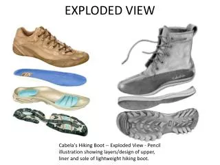
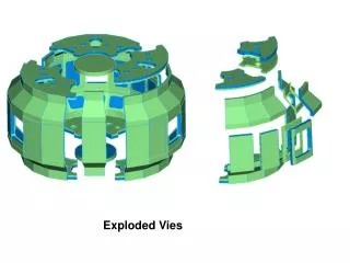
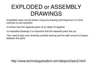
Exploded CAD Assembly Models. Exploded CAD Assembly Models. Also named Pictorial Assembly Exploded View Exploded Assembly Exploded Pictorial Exploded Assembly Presentation. Exploded CAD Assembly Models. Uses Repair manuals Owner’s manuals Sales promotion Customer self-assembly

E N D
Exploded CAD Assembly Models • Also named • Pictorial Assembly • Exploded View • Exploded Assembly • Exploded Pictorial • Exploded Assembly Presentation
Exploded CAD Assembly Models • Uses • Repair manuals • Owner’s manuals • Sales promotion • Customer self-assembly • Maintenance procedures
Direction Button • Specifies direction or axis of rotation of tweak • Click Direction button, then select an edge, face, or feature of any component in the graphics window to set the direction triad for the tweak
Components Button • Selects the components to tweak. Click the Components button, then select the components in the graphics window or browser • To remove a component from the group, press and hold the Ctrl key as you select
Trail Origin Button • Sets origin for the trail • Click the Trail Origin button, then click in the graphics window to set the origin point • If trail origin is not specified, then it is placed at the center of mass for the part
Display Trails • Sets display of trails • Select box to display the tweak trails for selected components • Clear the check box to hide trails • Turn trail visibility on or off by right clicking on tweak in the browser
Linear Transformations • Sets type of tweak to Linear • Click to select Linear, select the axis, enter the distance, and click the Apply button
Rotational Transformations • Sets tweak type as Rotational • Click Rotational, select rotation axis, enter degrees of rotation, and click Apply button
Direction of Transformations • Specifies the direction for a linear tweak or the axis for a rotational tweak • Select desired coordinate, then enter distance or rotation angle
Create Tweak • Creates a tweak using the current settings in the dialog box • Click to apply settings and create the tweak
Edit Existing Trail • Initiates edit mode for existing tweaks • Click to initiate the edit, select the tweak in the graphics window, then change the desired settings
Edit Existing Trail • Clears the settings in the dialog box so that you can set up another tweak • Tip: Click open space in the browser to clear only the component selection
Procedure • Click Create View button • Click Explore Directories button • Select Assembly file to use • Click OK
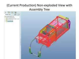
Tweak Components • Selected Assembly will be placed in graphics window as an isometric view • Select Tweak Components
Establish an Axis • Select an edge, face, or feature of any component in the graphics window to set the direction triad for the tweak • For rotational transformations, it may be best to establish the axis in the center of the part to be tweaked
Direction of Transformation • To set the direction of the transformation, click on either the button in the dialog box or the desired axis of the triad.
Select the Components • Select the component or group of components in the graphics window or browser • To remove a component from the group, press and hold the Ctrl key while selecting
Enter the Values • Enter desired distance of tweak • Click on green arrow button to confirm tweak • If tweak is not desired size, then change value and click on confirm arrow
Enter the Values • Click on Clear button • Begin process again by establishing a new axis