Download
1 / 14
140 likes | 148 Vues
RF acceleration and transverse damper systems. A. Butterworth AB/RF. Outline. System & controls overview 400MHz acceleration system (ACS) Transverse damper (ADT) Data sources Power systems Low-Level systems External diagnostics Triggering Remarks, status & conclusions.

E N D
RF acceleration and transverse damper systems A. Butterworth AB/RF
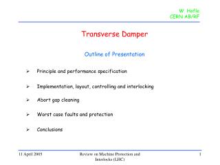
Outline • System & controls overview • 400MHz acceleration system (ACS) • Transverse damper (ADT) • Data sources • Power systems • Low-Level systems • External diagnostics • Triggering • Remarks, status & conclusions
400 MHz main acceleration system (ACS) 2 LHC rings = 2 independent RF systems • SC cavities (8 per ring) • 4 cryomodules of 4 cavities each • RF power system: • One klystron amplifier per cavity • RF power distribution system (waveguides, circulators, loads) • industrial controls (PLC) • Low Level system (fast RF controls): • cavity voltage and phase • beam phase and radial position • fast timing and beam synchronization • mostly digital, implemented in custom VME
Interlocks: RF interlock tree for one ACS RF line RF switch Timestamping (10us) VME module Software interlocks in PLC (10ms) Hardware interlock crates (5us) read out via PLC similar trees for HV and Beam interlocks
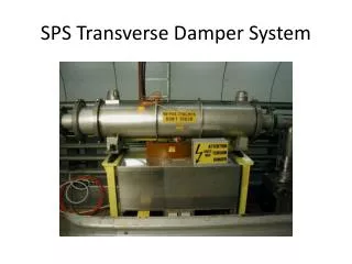
Transverse damper system (ADT) • Feedback system using electrostatic kickers to damp • injection oscillations • coupled bunch instabilities • Also excitation (measurements, abort gap cleaning) • 16 electrostatic kickers • 4 per plane (H/V) per beam • Power system: • amplifier chain with tetrode power amplifiers • industrial controls (PLC) • Low-Level signal processing • digital, custom VME • Fast interlocks cf. ACS beam Kicker tanks Tetrode power amplifiers 7.5 kV
Data: Power system/PLC controls • 20 PLCs for ACS 400 MHz acceleration system • 8 PLCs for ADT Transverse Damper • Supervision via FESA at 1 Hz • continuous values: powers, temperatures, pressures, flows • ~ 700 signals measurement system • statuses, faults, interlocks • ~ 150 signals measurement system • Interlock state changes (leading to RF or HV trip or beam interlock) • Software interlocks timestamped to 10ms precision in PLC • Hardware interlocks timestamped to 10us precision in dedicated VME module • “first fault” memorized • Interlock diagnostic performed in FESA alarm system
Data: Low level system embedded diagnostics • Circular memory buffers incorporated in Low-Level VME boards • 3.2 ms @ 80 MS/s (36 turns) • 6 s @ 20 kS/s • sampling synchronous with RF • data tagged with revolution frequency clock • need correlation with UTC? • total of ~ 256 MB for ACS system • total of ~ 32 MB for ADT system • 2 independent buffer sets: • Post Mortem • User (“Observation”)
Data: Stand-alone analogue acquisition Transverse damper schematic • Fast analogue acquisition • ADT: pickup and amplifier chain diagnostics • cPCI fast digitizers, 8 bits at 80 MS/s • sampling synchronous with RF • 64 channels with 10 MB each (1000 turns at 80 MS/s) • total of 640 MB • Low-frequency analogue acquisition (samplers) • ACS: detected RF power signals and He pressure • cPCI ADCs sampling at ~1 kHz • 98 channels, record length ~ few seconds • total of ~ 1 MB
RF frequency monitoring & beam diagnostics • RF frequency monitoring and interlock (1 per ring) • VME Trigger Unit (VTU) used as 400MHz counter • updated at 20 Hz • used to generate beam interlock if outside limits • circular history buffer in FEC (few minutes) • ~ 50 kB • APW wideband wall current monitor signal (1 per ring) • digitized at 8 GS/s, up to 170 turns • 256 MB could be made available for PM • bunch length & longitudinal emittance extracted at ~ 1 Hz • measurement system
Triggering • The 2 rings are independent: separate buffers are used for Beam1 and Beam 2 • PM timing event used to freeze: • fast (80 MS/s) stand-alone analogue acquisition • slow (1 KS/s/) analogue acquisition • RF frequency measurement (20 Hz) • Many of the embedded PM buffers in the Low-Level VME boards have very short recording time (3 or 6 ms) • latency of PM event (< 2ms) may cause significant loss of data • BIS status signal distributed to all Low-Level VME crates and can be used to trigger buffer freezing • PM timing event used to initiate data upload and re-arm • In the case of dump without PM (e.g. inject and dump), re-arm after a few ms timeout
Remarks: Pre-processing and analysis • Fast PM buffer data volumes: • embedded diagnostics ~ 300MB • stand-alone analogue signal diagnostics ~ 640MB • not clear how this can be reduced by pre-processing • simple pre-analysis with extraction of gains, phases, signal levels etc. and their comparison with reference values might be possible in the Front-End • more sophisticated analysis will require expert intervention • will not have such tools on day one • simple signal visualization is a good starting point
Current status and conclusions • PM buffers designed into the Low-Level equipment • Additional buffers provided via stand-alone systems where needed • Readout is an integral part of the FESA front-end software • Transmission of data to the PM system is still to be implemented • Other data for correlation: • Slow data from power equipment will be acquired in Measurement and Logging systems • Interlocks will result in an accurately timestamped alarm in LASER Should a snapshot be added into the PM record? • Concentrate initially on providing the necessary data, sophisticated analysis tools will come later