Download
1 / 16
160 likes | 266 Vues
DC Detection Experiment at the 40m Lab. Robert Ward for the 40m Lab to the AIC group Livingston LSC meeting March 22, 2005. Heterodyne & homodyne readouts. Heterodyne: traditional RF modulation/demodulation RF phase modulation of input beam

E N D
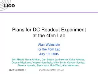
DC Detection Experiment at the 40m Lab Robert Ward for the 40m Lab to the AIC group Livingston LSC meeting March 22, 2005
Heterodyne & homodyne readouts • Heterodyne: traditional RF modulation/demodulation • RF phase modulation of input beam • Lengths chosen to transmit first-order RF sideband(s) to anti-symmetric output port with high efficiency • Initial LIGO: RF sidebands are in principal balanced at AS port • AdLIGO: with detuned RSE, one RF sideband is stronger than the other • RF sideband(s) serve as local oscillator to beat with GW-produced field • Signal: amplitude modulation of RF photocurrent • Homodyne: DC readout • Main laser field (carrier) serves as local oscillator • Signal: amplitude modulation of GW-band photocurrent • Two components of local oscillator, in DC readout: • Field arising from loss differences in the arms • Field from intentional offset from dark fringe Some linear component No slope
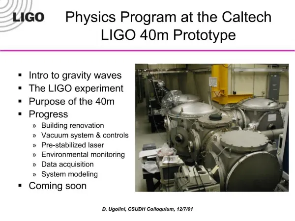
Why DC Readout at the 40m? • Homodyne detection (via a DC readout scheme) has been chosen as the readout scheme for AdLIGO. • DC Readout eliminates several sources of technical noise (mainly due to the RF sidebands): • Oscillator phase noise • Effects of unstable recycling cavity. • The arm-filtered carrier light will serve as a heavily stabilized local oscillator. • Perfect spatial overlap of LO and GW signal at PD. • It also avoids NEW noise couplings in detuned RSE due to unbalanced RF sidebands at the dark port. • DC Readout has the potential for QND measurements, without major modifications to the IFO. • The 40m is currently prototyping a suspended, power-recycled, detuned RSE optical configuration for AdLIGO. A complete prototyping of the AdLIGO optical configuration, in our view, includes the readout method. • We can also prototype innovations for LIGO I (see Rana’s talk).
What will we learn? • We’re not likely to see any quantum effects, given our noise environment. We may not even see any noise improvements. • The most important thing we will learn is : How to do it • How to lock it? • How best to control the DARM offset? • What are the unforeseen noise sources associated with an in-vacuum OMC? • How do we make a good in-vac photodiode? What unforeseen noise sources are associated with it? • We hope to discover any unforeseen pitfalls. • We will also perform as thorough an investigation as we can regarding noise couplings in detunedRSE, with both heterodyne and homodyne detection. • Parallel modeling and measurement studies.
A little context • The 40m Lab is currently not even close to being limited by fundamental noise sources.
Making the DClocal oscillator • Two components • Carrier field due to loss differences (not controllable?) • Carrier field due to dark fringe offset (controllable) • An output mode cleaner should take care of the rest. • Loss mismatch component • Average arm round trip loss: 75 ppm • Difference between arms: 40 ppm • Output power due to mismatch: 40 µW • Detection angle, β • Tuned by adjusting fringe offset • Angle of GW is frequency dependent in detuned RSE • Homodyne angle of Buanonno & Chen? LIGO I GW parallel to DC offset Detuned RSE: GW signal gets f-dependent phase shift in SRC fringe offset β Loss mismatch
DC Readout GW Transfer Functions • DC Readout GW Transfer Functions, using different amounts of DC offset • This changes the ‘Detection Angle’ as well as the amplitude of the LO. • We’ll look at a 19pm offset for reference. For AdLIGO, this will likely not be feasible. • Modeling done in FINESSE.
Controlling DARM • I can think of 4 options to control an offset DARM: 1. Standard RF (PDH) control, with a digital offset. 2. A standard DC locking scheme, with an offset. 3. A wacky DC locking scheme, like we do with the arms in our lock acquisition. 4. A wackier scheme involving the difference of the Arm cavity powers. • The linearity of 2-4 is …questionable.
DARM control signals • The Difference between the ARM powers gives a DARM signal! This is an effect of the detuned signal cavity. • Unsurprisingly, the square root of the dark port power also gives a nice DARM signal in a certain region.
DARM control signals, zoomed • A 19 picometer offset is well into the linear regime of the AP power signal. The LO power is about 9mW (for 1W after the MC). • Note that the TRX-TRY signal has an offset due to the loss mismatch.
But what happens to CARM? • Unsurprisingly, CARM gets a small offset too. Ideally, CARM will have no offset; this isn’t realistic, as it depends exquisitely on the demodulation phase. • Effect on the CM servo? • Power at the BS is reduced by 3%
The Output Mode Cleaner • We can use a 3 or 4-mirror OMC. • Off the shelf mirrors. • An easy spacer (Al?) • Cheap, quick, and easy to re-do. • Finesse ~ 500 • In-vacuum, on a seismic stack. • Considerations: • Astigmatism, counter propagating modes, accidental HOM resonances, RF sideband suppression. • Measurement of AP beam structure.
Controlling the OMC • OMC length signal: • Dither-lock? • Should be simple; we’ll try this first. • PDH reflection? • There’s only one sideband, but it will still work. • Servo: • Will proceed with a simple analog servo, using a signal generator and a lock-in amp. • Feedback filters can easily be analog or digital. • Can use a modified PMC servo board for analog. • Can use spare ADC/DAC channels in our front end IO processor for digital. • PZT actuation
The DC Detection diode • Ben Abbott has designed an aluminum stand to hold a bare photodiode, and verified that the block can radiate 100 mW safely. • Electronic signal amplification will occur immediately outside the vacuum chamber. We will be susceptible to any magnetic fields inside the chamber. • Another option is a diode in a can filled with an inert, RGA detectable gas; this will allow a similar electronic amplification stage to what we do now.
OMC Beam Steering :A preliminary layout is ready to go The Diode Existing in-vac seismically isolated optical table Mike Smith has designed a compact, monolithic MMT, similar to our input MMT. We’ll be using spherical mirrors. This will actually be the second PZT steering mirror. The first mirror after the SRM will also be a PZT steering mirror. from SRM From SRM
Further Plans • Quantify: • ISS requirements. • Just how bad is having the ISS pickoff after the Mach-Zehnder? • In-vac sensing? • Study MZ phase noise effects • PRC/SRC/MICH/DARM loop couplings • OMC length couplings • Ready for a review in mid/late April • How much do fluctuations in the loss mismatch ‘quadrature’ couple into the GW signal? • Sensing the OMC-input beam alignment?