Download
1 / 32
330 likes | 462 Vues
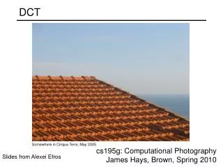
Directional DCT. K. R. RAO. Presented by, -Shreyanka Subbarayappa, Sadaf Ahamed , Tejas Sathe , Priyadarshini Anjanappa. Conventional Framework for Image Coding [9]

E N D
Directional DCT K. R. RAO Presented by, -Shreyanka Subbarayappa, SadafAhamed, TejasSathe, PriyadarshiniAnjanappa
Conventional Framework for Image Coding [9] The 2-D discrete cosine transform (DCT) of a square or a rectangular block shape is used for almost all block-based transform schemes for image and video coding. The NXM 2D-DCT is defined as Forward 2D DCT x(n,m)= Samples in the 2D data domain. X (k,l)= Coefficients in the 2D- DCT domain.
INVERSE 2D-DCT • The conventional 2D DCT: • Implemented separately through two 1-D transforms, one along the vertical direction and another along the horizontal direction. • These two processes can be interchanged • The conventional DCT seems to be the best choice for image blocks in which vertical and/or horizontal edges are dominating. • A popular scenario in many image signals- Image blocks containing directional edges + (M 1D-DCT s of Length N)
New Framework for Image Coding [2] • Directional DCT [2] [3]: • A new block based DCT framework in which the first transform may choose • to follow a direction other than the vertical or horizontal one. • Coefficients produced by all directional transforms in the first step are arranged appropriately; the second transform can be applied to the coefficients that are best aligned with each other. • Compared with the conventional DCT, the resulting directional DCT framework is able to provide a better coding performance for image blocks that contain directional edges. • Choose the best “directional” DCT according to the dominating edge(s) within each individual image block. Mode3: Diagonal Down Left Mode4: Diagonal Down Right
Limitations of Conventional DCT • It is not very efficient when the conventional DCT is applied to an image block in which other directional edges dominate. • When the first 1-D DCT (vertical or horizontal) is applied, the nonzero coefficients are not well aligned across different columns (or rows). • Consequently, the second 1-D DCT may produce more nonzero coefficients.
The different directional modes [5] 2 D (8X8) D-DCT Fig1: Six directional modes forthe block size 8x8 (The vertical and horizontal modes are not included here)
Mode3 D-DCT (4X4) Block [8] STEP 1: STEP 2: STEP 3: • (X00, X01,…… ,X32, X33)- Pixels in the 2-D spatial domain. • 1D- DCT is performed for the 4X4block in diagonal down-left position with lengths L=1, 2, 3, 4, 3, 2, 1 • (A,B,C,……O,P)- coefficients in the DCT domain. STEP 1: STEP 2: • The coefficients of step2 after 1D DCT are arranged vertically as shown in the figure. • Apply Horizontal 1D- DCT for lengths L=7, 5, 3 and 1 and arranged in the same pattern STEP 3:
STEP 4: • Apply Horizontal 1D- DCT for lengths L=7, 5, 3 and 1, the coefficients are arranged in the same pattern as shown in the figure STEP 5: • After Step 4, move all 2D (4X4) Directional DCT coefficients to the left. • Implement quantization followed by 2D VLC for compression/coding along zig-zag scan. • This scanning helps to increase the runlength of zero (transform) coefficients leading to reduced bit rate in the 2D-VLC coding (similar to JPEG [12]).
Basis Images For Mode34X4 Block STEP 1: • DCTs of lengths 1, 2, 3, 4, 3, 2, 1. • DCT of length 1 means same as the original pixel • When all pixels are zero of any length, then • the corresponding length DCT yields only zeros STEP 2: Repeat the procedure till you get this
Directional DCT for Mode 3 [5] Fig2: The first 1D DCT: • NxNimage block in which the first 1D DCT will be performed along the diagonal down-left direction.
The coefficients after the D-DCT(mode3) are arranged in this manner vertically. Fig3: The second 1D DCT: Horizontal DCTs of Length 15 13 11 9 7 5 3 1 • 1D DCT horizontally with lengths L=15, 13, 11, 9,7,5,3 and 1 • TO GET BACK THE ORIGINAL IMAGE ( INVERSE DIRECTIONAL DCT ) : • 1D IDCT horizontally with lengths L=15, 13, 11,9,7,5,3,1. • Put back the coefficients in the Fig2 for 8X8 block. • 1D IDCT directionally as shown in Fig2 and put back the coefficients in the same order. The output image is same as the original image.
DIRECTIONAL DCT MODE3 OUTPUT [5] 8X8 Block (Diagonal Down Left) For LENA IMAGE : mse = 1.0245e-027, PSNR = 318.0255dB • Note that no quantization and coding steps are involved. The errors are due to roundoff/truncation in implementing the forward and inverse 2D directional DCTs.
BASIS IMAGES FOR MODE3 [5] Diagonal Down Left Horizontal IDCTs of Length 15 13 11 9 7 5 3 1 Fig5 Fig4 • Keep the 1st coefficient as 1 and the remaining as zeros. Compute IDCT horizontally. • Put back the coefficient in the Fig5. • Compute 1D IDCT along the diagonal down-left direction and put back the coefficients in the same order back into the block. • The resulting block is 1 basis image • Repeat the same steps with the second coefficient as 1 and the remaining zero and computing IDCT horizontally and diagonal down left. The output thus obtained is 2nd basis image.. • Repeat the same procedure for L=15, 13, 11, 9, 7, 5, 3 and 1 to get the remaining 64 basis images
BASIS IMAGES FOR MODE3 Diagonal Down Left FOR4X4
FOR MODE3 8X8 (Diagonal Down left)
Directional DCT for Mode 4 [5] Horizontal DCTs of Length 15 13 11 9 7 5 3 1 Fig6: 1D DCT along Diagonal down-right Fig7: 1D DCT horizontally • NxN image block in which the first 1D DCT will be performed along the diagonal down-right direction. • These coefficients are arranged vertically as shown in Fig7. • 1D DCT horizontally with lengths L=15, 13, 11, 9,7,5,3 and 1
TO GET BACK THE ORIGINAL IMAGE Mode4 ( INVERSE DIRECTIONAL DCT ) : • 1D IDCT horizontally with lengths L=15, 13, 11,9,7,5,3,1. • Put back the coefficients in the Fig6 for 8X8 block. • 1D IDCT directionally as shown in Fig6 and put back the coefficients in the same order. The output image is same as the original image. Diagonal Down Right DIRECTIONAL DCT MODE4 OUTPUT
BASIS IMAGES FOR MODE4 [5] Fig8 Fig9 • Keep the 1st coefficient 1 and the remaining zero. Compute IDCT horizontally. • Put back the coefficient in the Fig9 diagonal down-right. • Compute 1D IDCT along the diagonal down-right direction and put back the coefficients in the same order back into the block. • The resulting block is 1 basis image • Repeat the same steps with the second coefficient as 1 and the remaining zero and computing IDCT horizontally and diagonal down left. The output thus obtained is 2nd basis image. • Repeat the same procedure for L=15, 13, 11, 9, 7, 5, 3 and 1 to get the remaining 64 basis images
BASIS IMAGES FOR MODE4 D-DCT Diagonal Down Right FOR 4X4
Basis Images for 8X8 Mode4 D-DCT Diagonal Down Right
Directional DCT – Mode 5 (Vertical Down Right) 4 DCT of Length DCT of Length 9 9 9 9 7 7 7 7 DCT of Length 4 8 8 8 8 8 8 8 Fig11: The second 1D DCT horizontally Fig10: The first 1D DCT along the vertical down right direction. • 8X8 image block in which the first 1D DCT will be performed along the diagonal down-right direction. • These coefficients are arranged vertically as shown in Fig11. • 1D DCT horizontally with lengths L=9, 9, 9, 9, 7, 7, 7 and 7
TO GET BACK THE ORIGINAL IMAGE ( INVERSE DIRECTIONAL DCT ) : • 1D IDCT horizontally with lengths L=15, 13, 11,9,7,5,3,1 • Put back the coefficients in the Fig1 for 8X8 block. • 1D IDCT directionally as shown in Fig1 and put back the coefficients in the same order. The output image is same as the original image. Mode5 Vertical Down Right DIRECTIONAL DCT MODE5 OUTPUT
BASIS IMAGES FOR MODE5 IDCT of Length 9 9 9 9 7 7 7 7 IDCT of Length 4 8 8 8 8 8 8 8 Fig1: Horizontal IDCT Fig2: 1D IDCT along vertical down right • Keep the 1st coefficient 1 and the remaining zero. Compute IDCT horizontally. • Put back the coefficient in the Fig2 vertical down-right. • Compute 1D IDCT along the vertical down-right direction and put back the coefficients in the same order back into the block. • The resulting block is 1 basis image • Repeat the same steps with the second coefficient as 1 and the remaining zero and computing IDCT horizontally and vertical down left. The output thus obtained is 2nd basis image. • Repeat the same procedure for L=15, 13, 11, 9, 7, 5, 3 and 1 to get the remaining 64 basis images
BASIS IMAGES FOR 4X4 MODE5 D-DCT (Vertical Down Right) FOR 4X4
Basis Images for 8X8 Mode5 D-DCT (Vertical Down Right)
Procedure for obtaining the Directional DCT of a block and its reconstruction for MODES 6, 7 and 8: • Forward Directional DCT: • For the directional modes, the first 1D DCT is applied along the direction of the dominant edge in each block. • The second 1D DCT is along the horizontal direction in the rearranged pattern of the block. • Inverse Directional DCT: • To reconstruct the block, the first Inverse-DCT is applied along the horizontal direction. • The second Inverse-DCT is applied along the direction of the dominant edge in the block.
ZIG-ZAG SCANNING Mode3 Diagonal Down Left 8X8 Block Fig12: Arrangement of coefficients after the second DCT Fig13: Modified zigzag scanning • Figure13 shows all the coefficients (after the horizontal DCT) are shifted to the left. • ZigZag scanning is done after the second DCT shown in fig12. • Scanning is performed to group low frequency coefficients in top of vector • It performs quantization to round off most of the coefficients to zero or to the nearest level.
RESEARCH AREAS • Develop a directional DCT framework and demonstrate that it is able to provide a remarkable coding gain as compared to the conventional DCT • Embedded Directional DCT framework into H.264 [10] so that the corresponding directional DCT mode will be applied to an image block in combination with the best intra prediction chosen for this block. • How to independently select the best DCT mode effectively. • Directional DCTs can be extended to many existing international standards (for image and video coding)[10][11][12] that employ the conventional DCT. • By selecting the best suited one from seven directional modes for each image block, it can be demonstrated that a remarkable coding gain is achieved in the • rate-distortion coding performance. • Explore some other zig-zag scanning patterns appropriate for a particular directional mode leading to reduced bit count
Directional-Discrete Cosine Transform (D-DCT) • While D-DCT appears to provide remarkable coding gain compared to traditional DCT, the former inherently involves additional implementation complexity. • This complexity factor needs to be explored fully. Trade off between the coding gain and additional complexity needs to be taken into account.
REFERENCES • F. Kamisli and J. S. Lim, “Video compression with 1-d directional transforms in H.264/AVC”, IEEE ICASSP, pp-738-741, March 2010. • J. J. Fu and B. Zeng, “Directional discrete cosine transforms for image coding”, Advances in Multimedia Information Processing- PCM06, pp. 150-158, 2006. • B. Zeng and J. J. Fu, “Directional discrete cosine transforms for image coding”, IEEE ICME, pp.721-724, July 2006. • J. J. Fu and B. Zeng, “Directional discrete cosine transforms: a theoretical analysis,” IEEE ICASSP, vol.1, pp.1105-1108, April 2007. • B. Zeng and J. J. Fu, “Directional discrete cosine transforms- a new framework for image coding”, IEEE Trans. CSVT, vol. 18, pp. 305-313, March 2008. • A. Dremeau et al, “Sparse optimization with directional DCT bases for image compression”, IEEE ICASSP, pp.1290-1293, Dallas, Tx, March 2010. • C. L. Chang and B. Girod, “Direction-adaptive partitioned block transform for image coding”, IEEE International Conference on Image Processing (ICIP08), pp.145-148, Oct. 2008. • H. Xu, J. Z. Xu and F. Wu, “Lifting-based directional DCT-like transform for image coding”, IEEE Trans. CSVT, vol.17, pp. 1325-1335, July 2007. • K. R. Rao and P.Yip, “Discrete Cosine Transform”, Boca Raton, FL: Academic Press, 1990.
A. Puri, X. Chen and A. Luthra, “Video coding using the H.264/MPEG-4 AVC compression standard”, Signal Processing: Image Communication, vol. 19, pp. 793-849, Oct. 2004. 11. L. Yu et al, “Overview of AVS video coding standards,” Signal Processing: Image Communication, vol. 24, pp. 263-276, April 2009. 12. G. K. Wallace, “The JPEG still picture compression standard,” Communication of the ACM, vol. 34, pp. 31-44, April 1991.