Download
1 / 18
180 likes | 354 Vues
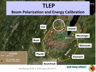
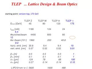
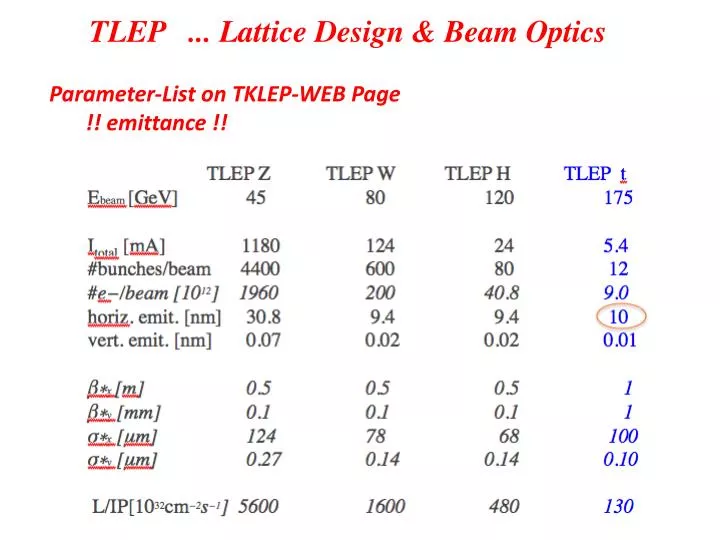
TLEP ... Lattice Design & Beam Optics. Parameter-List on TKLEP-WEB Page !! emittance !!. Reminder: TLEP . . . the very first steps. TLEP ... Lattice Design ... Version 1...2. Arc : 96 standard FoDo cells & 2 half bend cells at beginning and end length of arc: 2.8km

E N D
TLEP ... Lattice Design & Beam Optics Parameter-List on TKLEP-WEB Page !! emittance !!
Reminder: TLEP ... the very first steps
TLEP ... Lattice Design ... Version 1...2 Arc: 96 standard FoDo cells & 2 half bend cells at beginning and end length of arc: 2.8km length of straight section: 0.45 km Dx
TLEP ... Lattice Design Arc: the single FoDo cell until now ... 2 dipoles / 2 quadrupoles to be optimised according to hardware engineering short cell length: ≈ 30 m advantage: small betas small dispersion small emittance but: realistic hardware design ?
TLEP ... Lattice Design Arc:the single FoDo cell phase advance: 900 / 600 to be discussed ... 900 horizontally: small dispersion & emittance 600 vertically: small beam size (βy) and better orbit correction tolerance (LEP experience)
TLEP ... Lattice Design (175 GeV) not the very first steps anymore (... V9.e) Main modifications wrt. previous versions: longer cells to achieve higher dispersion values Text-Book like approach still 80 km, standard FoDo structure fill factor, robustness, easy to handle & modify easy to understand & optimise analytically Choice of single cell: compared to V.3 ...V.6 cell length increased to Lcell = 50m equilibrium emittance scaling of dispersion in a FoDo
TLEP ... single cell Lcell=50m Dipole: Ndipole = 2932 Ldipole = 21.3 m due to techn. reasons: 2 * 11 m bending angle = 2.14 mrad B0 = 580 Γ Quadrupole (arc): Lquadrupole = 1.5 m k=3.55*10-2 m-2 g=20.7 T/m aperture: r0=30σ =11mm Btip= 0.23 T β ≈ 100m, Dx= 15.3 cm FoDo Cell At present the dipole length is “symbolic”. Due to technical reasons we think of putting 2 dipoles of 11m length each between the quads
TLEP ... mini beta hardware L*= 4m Quadrupole (mini-β): Lquadrupole = 0.75 m k=0.43 m-2 g = k*Bρ ≈ 250 T/m aperture assumption: r0=30σ pole tip field: -> scale mini-β quad length to 7.5m B0 = 0.75 T * beam separation / crossing angle / synchrotron radiation / beam-beam interaction in the vicinity of strong quadrupole gradients
TLEP ... Lattice Design 24 Arcs : built out of 56 standard FoDo cells & 2 half bend cells at beginning and end length of arc: ≈ 3.0km each arc is embedded in dispersion free regions ... arcs are connected by straight. sections ... 12 long (mini β and RF) ... 12 ultra shortiestbc to be optimised
TLEP Octant Straight – Arc – Arc – Straight arcs are connected in pairs via a disp-free-empty cell -> only reason: in case of additional insertions we get the boundary conditions for free.
TLEP Arc-Straights 8 Straights : 9 empty (i.e. dispersion free) FoDo cells including matching sections arc-straight, l = 450m arc cells empty cells arc cells empty cells to be optimised: βy at matching section, needs an additional quadrupole lens already built in but not used yet. and / or optimisation of the lens positions
TLEP Mini-Betas 4 Mini-beta-Insertions : based on empty (i.e. dispersion free) FoDo cells L*=4m β*x =1m, β*y =1mm standard doublet structure & matching section βm,ax =18 km
TLEP The Ring rf-sections Lring = 79.9km 4 min- betas, 24 disp free straights, 12 long straights 8 for rf equipment, 4 for mini-betas & rf * * * * * * * * * * * *
TLEP ... new parameter list
TLEP ... Lattice Design V9.e beam dynamics of the ring Main Parameters: momentum compaction energy loss per turn: MADX: αcp=8.94*10-6 MADX: ΔU0=8.2 GeV
TLEP ... V 9.e Main Parameters: Damping & Beam Emittance Nota bene: Emittance is as before nicely small .. still smaller than the design value (2nm). however for a theoretical, ideal lattice without coupling, beam-beam, solenoid fields, tolerances error tolerances to be considered, how realistic is 2nm and 1 permille for εy/εx
Synchrotron Radiation Power 175 GeV, 80km Np= 9*1012 ΔU0 = 8.2 GeV T0 = 266 μs ... and Saw-Tooth effect (still without mini-beta) rf distributed over 12 straights and 216 cavities (60MV each)
Next steps: • * Optics fine tuning: including radiation effects • * Do we really need Dx= 15 cm or should we relax ?? • * Establish complete versions for different Mini Beta Options • local / global Q’ correction • * Optimise RF distribution • how many straights do we really need ??? • * Lattice for lower energies • beam separation ??? • * 80 km / 100 km ??? tbd • * start with the Ph.D. topics: • what about the momentum acceptance ??? • *** define a mid term parameter table ( t >> 2 days )