Download
1 / 11
150 likes | 384 Vues
Borehole Muography. 1 Earthquake Research Institute, the University of Tokyo, Japan 2 National Research Institute for Earth Science and Disaster Prevention, Japan. p. Purpose. Atmosphere. μ. μ. Fault. Typical surface detector cannot measure underground structures

E N D
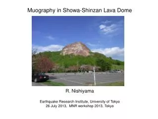
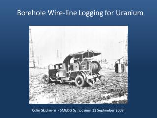
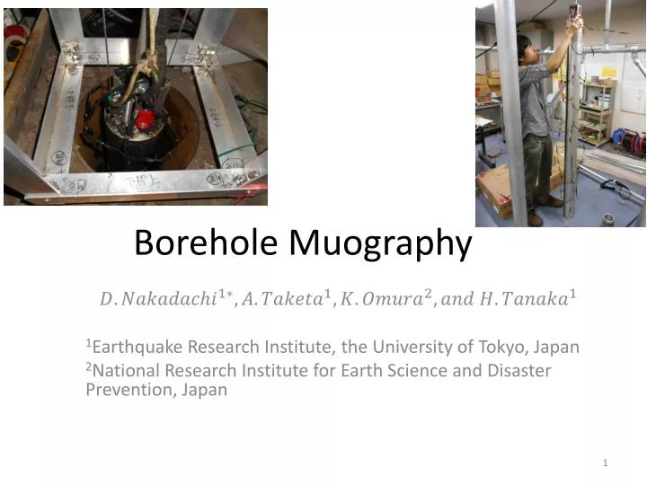
Borehole Muography 1Earthquake Research Institute, the University of Tokyo, Japan 2National Research Institute for Earth Science and Disaster Prevention, Japan
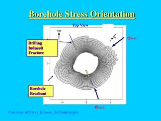
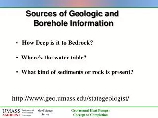
p Purpose Atmosphere μ μ Fault Typical surface detector cannot measure underground structures because muonsonly come from the sky How do we measure underground structure? →Put a detector into underground Detector There are boreholesnear the fault Extension to the underground of MUOGRAPHY Target : Fault zone structure -position,strike,dip ,width, and density →Prediction on seismic intensity BOREHOLE MUOGRAPHY
Development of a new method &detector 1m PMT Zenith Z • Traditional detector 1m×1m×1m →CANNOT be put into the borehole good angular resolution ~ 1° Muon Scintillator 1m Only 2 coupled scintillators are used Y X ~10 cm Borehole We count when muons come common section ・ New detector 4cm×7cm×70cm Angular resolution ~30° Need scanning in boreholes (rotation and up-down) 3
Sensitivity of the detector Two factors of sensitivity ・Shape of detector Most sensitive from perpendicular to the detector’s section ・Angular distribution of muons Most of muons come from vertical directions Horizontal muons are absorbed by the ground Zenith angle Muons Borehole Change angle Azimuth angle Change depth Detector Perpendicular to the section Perpendicular to the section Detector Using this detector as a probe, we count muons as a function of depth and azimuthal angle 4
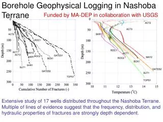
Test observation at Yayoi well (borehole) Does the detector have an ability to measure the density deficit of the low density area(Cavity) ? Well 20cm ~70m in depth C Yayoi well, located in U Tokyo, was dug by Earthquake Research Institute in 1897. A B D
4directions Observation D A Period: March~April, 2013 Points: Depth=10m~60m at 10m intervals 4 directions at 45°intervals Time: about 24h at each point C B Rods for directional control 200cm Interval : 10m Wire 12cm Detector
ResultDoes detector know the existence of cavity? A Ratio B Cavity is detected! Cavity 0.3g/cc Layer 2.0g/cc Cavity exists inthe direction A from well Counting rate A>Counting rate B Depth
Analysis Result:Density 50m 60° 10m Cavity Layer 1 10m Layer 2 3.0 2.5 2.0 1.5 1.0 0.5 0 Layer 3 10m Density ) Layers 300° 360° 360° 360° 360° 360° Cavity(60°) Using all 24 data points 0 10 20 30 40 50 60 Estimating density of layersand cavity simultaneously Depth
Summary • We developed a new method and a detector to measure the seismic fault zone from boreholes • Test observation at Yayoi well • We measured density deficit • Existence of cavity • Density of cavity and layers
Treatment of observation data Muon Events ) 100% Noise Muon Counts Pulse height Depth Data got by observation: Muon+noise counting rate(/s) →True muon’s counting rate (/s) Process1Process2 Cut noise by energy loss revise detection efficiency in 100% in the detector
Existence of cavity → Density of cavity Observation point according to depth and direction Counting rate (Simulation) in the point under the density model :Counting rate (Observation) in the point is optimum solution Layer-Cavity Model ・・・