Download
1 / 55
550 likes | 652 Vues
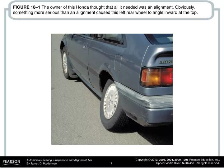
FIGURE 18–1 The owner of this Honda thought that all it needed was an alignment. Obviously, something more serious than an alignment caused this left rear wheel to angle inward at the top.

E N D
FIGURE 18–1 The owner of this Honda thought that all it needed was an alignment. Obviously, something more serious than an alignment caused this left rear wheel to angle inward at the top.
FIGURE 18–2 Magnetic bubble-type camber/caster gauge. To help it keep its strong magnetism, it is best to keep it stored stuck to a metal plate or metal tool box.
FIGURE 18–3 Typical tire wear chart as found in a service manual. Abnormal tire wear usually indicates a fault in a steering or suspension component that should be corrected or replaced before an alignment is performed.
FIGURE 18–4 Measuring points for ride (trim) height vary by manufacturer. (Courtesy of Hunter Engineering Company)
FIGURE 18–5 Measuring to be sure the left and right sides of the vehicle are of equal height. If this measurement is not equal side-to-side by as little as 1/8 in. (3 mm), it can affect the handling of the vehicle.
FIGURE 18–6 The bulge in this tire was not noticed until it was removed from the vehicle as part of a routine brake inspection. After replacing this tire, the vehicle stopped pulling and vibrating.
FIGURE 18–7 Equal outer CV joint angles produce equal steer torque (toe-in). If one side receives more engine torque, that side creates more toe-in and the result is a pull toward one side, especially during acceleration.
FIGURE 18–8 Broken or defective engine or transaxle mounts can cause the powertrain to sag, causing unequal drive axle shaft CV joint angles.
FIGURE 18–9 This alignment chart indicates the preferred setting with a plus or minus tolerance.
FIGURE 18–10 Using the alignment rack hydraulic jacks, raise the tires off the rack so that they can be rotated as part of the compensating process.
FIGURE 18–11 This wheel sensor has a safety wire that screws to the valve stem to keep the sensor from falling onto the ground if the clamps slip on the wheel lip.
FIGURE 18–12 If toe for an oversize tire is set by distance, the toe angle will be too small. Toe angle is the same regardless of tire size.
FIGURE 18–13 The protractor scale on the front turn plates allows the technician to test the turning radius by turning one wheel to an angle specified by the manufacturer and observing the angle of the other front wheel. Most newer alignment machines can display turning angle based on sensor readings, and therefore the protractor scale on the turn plate is not needed or used.
FIGURE 18–14 By checking the SAI, camber, and included angle, a damaged suspension component can be determined by using this chart.
FIGURE 18–15 In this example, both SAI and camber are far from being equal side-to-side. However, both sides have the same included angle, indicating that the frame may be out of alignment. An attempt to align this vehicle by adjusting the camber on both sides with either factory or aftermarket kits would result in a totally incorrect alignment.
FIGURE 18–16 This is the same vehicle as shown in Figure 18–15, except now the frame (cradle) has been shifted over and correctly positioned. Notice how both the SAI and camber become equal without any other adjustments necessary.
FIGURE 18–17 Geometric-centerline-type alignment sets the front toe readings based on the geometric centerline of the vehicle and does not consider the thrust line of the rear wheel toe angles. (Courtesy of Hunter Engineering Company)
FIGURE 18–18 Thrust line alignment sets the front toe parallel with the rear-wheel toe. (Courtesy of Hunter Engineering Company)
FIGURE 18–19 Four-wheel alignment corrects for any rearwheel toe to make the thrust line and the geometric centerline of the vehicle both the same. (Courtesy of Hunter Engineering Company)
FIGURE 18–20 The rear camber is adjustable on this vehicle by rotating the eccentric cam and watching the alignment machine display.
FIGURE 18–21 Some vehicles use a threaded fastener similar to a tie rod to adjust camber on the rear suspension.
FIGURE 18–22 Aftermarket alignment parts or kits are available to change the rear camber.
FIGURE 18–23 Full-contact plastic or metal shims can be placed between the axle housing and the brake backing plate to change rear camber, toe, or both. (Courtesy of Northstar Manufacturing Company, Inc.)
FIGURE 18–24 The rear toe was easily set on this vehicle. The adjusting nuts were easy to get to and turn. Adjusting rear toe is not this easy on every vehicle.
FIGURE 18–25 By moving various rear suspension members, the rear toe can be changed.
FIGURE 18–26 The use of these plastic or metal shims requires that the rear wheel as well as the hub assembly and/or backing plate be removed. Proper torque during reassembly is critical to avoid damage to the shims.
FIGURE 18–27 Many struts allow camber adjustment at the strut-to-knuckle fasteners. Here a special tool is being used to hold and move the strut into alignment with the fasteners loosened. Once the desired camber angle is achieved, the strut nuts are tightened and the tool is removed.
FIGURE 18–28 Some struts require modification of the upper mount for camber adjustment.
FIGURE 18–29 An example of the many methods that are commonly used to adjust front caster and camber.
FIGURE 18–30 If there is a nut on both sides of the strut rod bushing, then the length of the rod can be adjusted to change caster.
FIGURE 18–31 Placing shims between the frame and the upper control arm pivot shaft is a popular method of alignment for many SLA suspensions. Both camber and caster can be easily changed by adding or removing shims.
FIGURE 18–32 The general rule of thumb is that a 1/8-in. shim added or removed from both shim locations changes the camber angle about 1/2 degree. Adding or removing a 1/8-in. shim from one shim location changes the caster by about 1/4 degree.
FIGURE 18–33 Some SLA-type suspensions use slotted holes for alignment angle adjustments. When the pivot shaft bolts are loosened, the pivot shaft is free to move unless held by special clamps as shown. By turning the threaded portion of the clamps, the camber and caster can be set and checked before tightening the pivot shaft bolts.
FIGURE 18–34 When the nut is loosened and the bolt on the eccentric cam is rotated, the upper control arm moves in and out. By adjusting both eccentric cams, both camber and caster can be adjusted.
FIGURE 18–35 Typical shim alignment chart. As noted, 1/8-in. (0.125) shims can be substituted for the 0.120-in. shims; 1/32-in. (0.0625) shims can be substituted for the 0.060-in. shims; and 1/32-in. (0.03125) shims can be substituted for the 0.030-in. shims.
FIGURE 18–36 Many procedures for setting toe specify that the steering wheel be held in the straight-ahead position using a steering wheel lock, as shown. One method recommended by Hunter Engineering sets toe without using a steering wheel lock.
FIGURE 18–37 Adjusting toe by rotating the tie rod on a vehicle equipped with rack-and-pinion steering.
FIGURE 18–38 Toe is adjusted on a parallelogram-type steering linkage by turning adjustable tie rod sleeves. Special tie rod sleeve adjusting tools should be used that grip the slot in the sleeve and will not crush the sleeve while it is being rotated.
FIGURE 18–39 Special tie rod adjusting tools should be used to rotate the tie rod adjusting sleeves. The tool grips the slot in the sleeve and allows the service technician to rotate the sleeve without squeezing or damaging the sleeve.
FIGURE 18–40 Most vehicles have alignment marks made at the factory on the steering shaft and steering wheel to help the service technician keep the steering wheel in the center position.
FIGURE 18–41 A puller being used to remove a steering wheel after the steering wheel retaining nut has been removed.
FIGURE 18–42 The toe-in on the right wheel creates a turning force toward the right.
FIGURE 18–43 (a) Aftermarket camber kit designed to provide some camber adjustments for a vehicle that does not provide any adjustment. (b) Installation of this kit requires that the upper control arm shaft be removed. Note that the upper control arm was simply rotated out over the wheel pivoting on the upper ball joint.
FIGURE 18–44 (a) The installation of some aftermarket alignment kits requires the use of special tools such as this cutter being used to drill out spot welds on the original alignment plate on a strut tower. (b) Original plate being removed. (c) Note the amount of movement the upper strut bearing mount has around the square openings in the strut tower. An aftermarket plate can now be installed to allow both camber and caster adjustment.
FIGURE 18–45 A typical tire temperature pyrometer. The probe used is a needle that penetrates about 1/4 inch (7 mm) into the tread of the tire for most accurate readings.
FIGURE 18–46 Jig holes used at the assembly plant to locate suspension and drivetrain components. Check service information for the exact place to measure and the specified dimensions when checking for body or frame damage.