Download
1 / 72
720 likes | 834 Vues
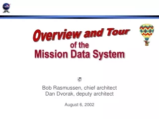
Overview and Tour. of the Mission Data System. Bob Rasmussen, chief architect Dan Dvorak, deputy architect August 6, 2002. Outline. Overview Motivations, vision, themes A Virtual Tour A balloon ride down into the depths of MDS State Analysis Process

E N D
Overview and Tour of theMission Data System Bob Rasmussen, chief architect Dan Dvorak, deputy architect August 6, 2002
Outline • Overview • Motivations, vision, themes • A Virtual Tour • A balloon ride down into the depths of MDS • State Analysis Process • Questions and answers about how things work • MDS Implementation Status • Questions & answers
Challenging Future Missions • In situ exploration • Multi-vehicle coordination • More complex observatories • An interplanetary network
Pressures for Autonomy • Uncertain environments • Opportunistic observations • More severe constraints
More Complex Tasks • Interact with and alter the environment • Alter plans to achieve objectives • Coordinate multiple competing activities • Manage resources • intelligently screen data before transmission
Historical Gaps • Between expressing what operators want and expressing how to get it • Between flight and ground software developments • Between missions in inheritance of flight software • Between ground generated time-based sequencing and fault tolerance • Between systems and software engineering
No Pressures for Change • New era of more frequent launches • Demands for lower cost • Specter of mission-ending failuresdue to errors in software • Success must be assured,despite large uncertainties
Yes What We Need • Highly reusable core software for flight, ground, and test • Synergistic systems & software engineering • Reduced development time and cost • Improved development processes • Highly reliable operations • Increased autonomy
The MDS Vision A unified control architecture and methodsfor flight, ground, and test systemsthat enable missionsrequiring reliable, advanced software
What is MDS … Really? • An architecture, unifying flight, ground, & test systems • An orderly systems engineering methodology • Software frameworks (C++ and Java) • Processes, tools, and documentation • Working examples of adaptation • Reusable software components
Achieving the Vision • MDS project started in 1998 • Initial focus on analysis and prototyping • Full implementation initiated in 2001 • Design and implementation of core frameworks near completion — continuing updates • Current focus on maturation through application to real systems • Running on Rocky 7 and FIDO rovers • Baselined for Mars Smart Lander project
MDS Themes • Construct subsystems from architectural elements, not the other way around • Some things go together — others do not • Be explicit (use goals, models, …) • Close the loop • Think ahead A unified approach to managing interactions is essential
Events Fault Detection Goals Estimation Planning State Measurements Sequencing Simulation Telemetry Parameters Archiving Visualization A State-Based Approach • Formally recognize state as the key system concept • Make state the central organizing theme for most functions • Express all knowledge in models of state • Share a common definitionof system state among models
Component Connector A Component-Based Approach • The State Architecture establishes the elements of functionality, but not the software design • The Component Architecture establishes the elements of software design • Issues are raised to the levelof symbolic realization • Software is organizedas components • State-based elements arerealized as components • Complexity of interactions is managed at the component level
State-BasedArchitecture • Handles interactionsamong elementsof the system under control • Outward looking • Addresses systemsengineering issues • Component-Based • Architecture • Handles interactionsamong elementsof the system software • Inward looking • Addresses softwareengineering issues Complementary Approaches
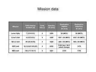
25 Missions in Next 10 Years A-3 Next: MFRM
JPL Mars Future Rover Mission (MFRM) MDS Inside A-4 Next: inside
Inside Mission MFRM JPL MFRM <<deployment>> Rover <<deployment>> Lander <<deployment>> Ground UML notation for deployments A-5 Next: Lander
<<discipline>> Science <<discipline>> GNC <<discipline>> Pyro <<discipline>> Power <<discipline>> Avionics <<discipline>> Thermal <<discipline>> Telecom <<discipline>> Data Products Inside Lander JPL MFRM Lander A-6 Next: Thermal
Inside Thermal, Depth 1 JPL MFRM Lander Thermal - depth 1 UML notation for component connection A-7 Next: closer
<<state variable>> Camera Temperature Sensor Health State Variable <<state variable>> Camera TemperatureState Variable <<estimator>> Camera Temperature Estimator <<controller>> Camera Temperature Controller <<hardware proxy>> CameraHardware Proxy Inside Thermal, depth 2 JPL MFRM Lander Thermal - depth 1 - depth 2 state estimates goals estimate functions commands, status measurements UML notation for component A-8 Next: state architecture
Outside a State Variable • JPL • MFRM • Lander • Thermal • - depth 1 • depth 2 • state var • -outside UML notation for interfaces Camera TemperatureState Variable State query State update Notification Policy control UML notation for component Direction of call A-10 Next: query interface
Looking at an Interface JPL MFRM Lander Thermal - depth 1 - depth 2 state var -outside -interface UML notation for an interface class Template argument EstimateType <<interface>> State Query Interface getState(const Epoch& time): RefCountPtr<const EstimateType> Return type Operation Arguments RefCountPtr Epoch A-11 Next: inside SV
Now Past Future continuous-valued variable ON Don’t Know ON ON Don’t Care ON OFF OFF OFF OFF discrete-valued variable time Inside a State Variable JPL MFRM Lander Thermal - depth 1 - depth 2 state var -outside -interface -inside A timeline represents a state variable’s value as a function of time Estimates states (knowledge) Planned states (intent) A-12 Next: back to Thermal
<<state variable>> Camera Temperature Sensor Health State Variable <<state variable>> Camera TemperatureState Variable <<estimator>> Camera Temperature Estimator <<controller>> Camera Temperature Controller <<hardware proxy>> CameraHardware Proxy Inside Thermal, depth 2 JPL MFRM Lander Thermal - depth 1 - depth 2 state estimates goals estimate functions commands, status measurements A-13 Next: goal
State Analysis A gradual, methodical discovery process … … that systems engineers use … … to ask and answer questions about how things work
? m ? m ? m m m ? ? m ? ? m m m ? m ? State Analysis is Recursive • It is a gradual discovery process, prompted by a standard set of basic questions • The answer to each question is a piece of the model • Each answer prompts additional questions, and so on • The model unfolds a step at a time in terms of commonframework elements until all the pieces are identified question model
State VariablesUnderstanding the System in Terms of State • Start with a few key states • Look at their behaviors • Ask how and why they change • Revisit this for every new state variable that is identified Define aState Variable Do other states affect it? What other statesare involved? Model an Effect Each model element gets at least a name and a description. Most have several other characteristics and links to other elements that must be described.
Spacecraft States • Dynamics • Vehicle position & attitude, gimbal angles, wheel rotation, … • Environment • Ephemeris, light level, atmospheric profiles, terrain, … • Device status • Configuration, temperature, operating modes, failure modes, … • Parameters • Mass properties, scale factors, biases, alignments, noise levels, … • Resources • Power & energy, propellant, data storage, bandwidth, … • Data product collections • Science data, measurement sets, … • DM/DT Policies • Compression/deletion, transport priority, … • Externally controlled factors • Space link schedule & configuration, … … and so on
Spacecraft Models • Relationships among states • Power varies with solar incidence angle, temperature, & occultation • Relationships between measurement values and states • Temperature data depends on temperature, but also on calibration parameters and transducer health • Relationships between command values and states • It can take up to half a second from commanding a switch to full on • Sequential state machines • Some sequences of valve operations are okay; others are not • Dynamical state models • Accelerating to a turn rate takes time • Inference rules • If there has been no communication from the groundin a week, assume something in the uplink has failed • Conditional behaviors • Pointing performance can’t be maintained until rates are low • Compatibility rules • Reaction wheel momentum cannot be dumped while being used for control … and so on
Choose carefully how each state will be expressed This is driven by need Uncertainty must be part of the definition Value histories maintain state values as functions of time They record the past They may also predict the future They are transported across space links to report what is happening Policies guide the treatment of this data This includes converting it into new forms State Value HistoriesReporting What’s Happening in Terms of State Define aState Variable How should the statebe represented? Define State Functions How should statebe managed & transported? Define a Policy
Measurement models describe how measurement data is related to state Usually sensors measure many more states,in addition to the ones intended Newly identified states prompt more questions Measurements are also kept in value histories Sensors (Input Devices) Define aState Variable Can it be measured? Define a Sensor What measurements does it produce? How should measurementsbe managed & transported? Model a Measurement Define a Policy What other states does it measure?
Command models describe changes to state Often commands affect other states, in addition to the ones intended Newly identified states prompt more questions Commands are also kept in value histories Actuators (Output Devices) Define aState Variable Can it be directly commanded? Define an Actuator What commands does it accept? How should commandsbe managed & transported? Model a Command Define a Policy What other states does it affect?
Hardware Adapters • Sensors and actuators are input and output ports, respectively on hardware adapters • Hardware adapters handle all communication with the hardware • They may also augment hardware capabilities with various low level services • Collectively, these hardware and service functions present architecturally uniform sensor and actuator ports to the rest of the software Define a Sensor Define an Actuator Define a H/W Adapter
Models suggest how states should be estimated Estimators often use models directly You may identify multiple ways to know a state, depending on circumstances and need State DeterminationMonitoring the System and Its Own Actions to Determine State Define aState Variable How should state knowledge be updated? How well must the state be known? Model an Effect Define a Knowledge Goal Model a Command Model a Measurement How will this be achieved? Define an Estimator • Estimators are “goal achievers”
Models can also suggest how states should be controlled Controllers often use models directly There are usually several ways to control a state State ControlActing on the System to Control Its State Define aState Variable How must the state be controlled? Model an Effect Define aControl Goal Model a Command How will this be achieved? Define a Controller • Controllers are also “goal achievers”
ElaborationExpressing Intention in Terms of Desired State Model an Effect • When states can’t be commanded directly, control other states that affect them instead — and don’t forget to allocate side effects • Elaboration identifies new goals, and so on What other states can be used to change this state? What other states does this state affect? Define aState Variable Define aGoal How should related states be controlled? How should side effects be allocated? Are all needed goals defined? Define an Elaboration
Constraint Networks • Goals elaborate recursively into constraint networks • These are scheduled across state timelines, describing a scenario State 1 Goal State 2 Goal Goal Goal Goal Goal Goal Goal Goal Goal Goal Time
m ? m m ? m ? ? m m ? m m ? m ? m m ? ? m m ? ? Following Leads — An Example Standard Questions: Common FrameworkElements: ? What do you want to achieve? Goal • Move rover to rock What’s the state to be controlled? State Variable • Rover position relative to rock What evidence is there for that state? Measurements • IMU, wheel rotations,sun sensor, stereo camera What does the stereo camera measure? • Distance to terrain features,light level, camera power (ON/OFF), camera health Measurement Model How do you raise the light level? State Effects Model • Wait until the sun is up Where is sun relative to horizon? Etc. • …
State Database ServerA Tool for State Analysis Screen display of browser during state analysis
<<state variable>> Camera Temperature Sensor Health State Variable <<state variable>> Camera TemperatureState Variable <<estimator>> Camera Temperature Estimator <<controller>> Camera Temperature Controller <<hardware proxy>> CameraHardware Proxy Inside Thermal, depth 2 JPL MFRM Lander Thermal - depth 1 - depth 2 goals state estimates estimate functions commands, status measurements A-13 Next: goal
state variable state constraint start time end time Goal State Variable State Constraint start Epoch end Camera Temperature Goal JPL MFRM Lander Thermal - depth 1 - depth 2 Goal Adaptation Camera Temperature Goal camera temperature between 280oK and 290oK from 2008-05-15T18:00:00ET until 2008-05-15T19:00:00ET Framework A-14, click Next: ascending to Goal Net package
A Framework Package JPL MFRM Lander Thermal Goal Net Goal Net Goal GoalStatus GoalNet XGoal TemporalConstraint TimePoint NetworkTree GoalTree ... Tactic GoalElaborator A-15 Next: ascending to Thermal
Camera Temperature Sensor Health State Variable Camera TemperatureState Variable VH SI Ep ... Cmp Cmp VH Ep ... Camera Temperature Estimator Camera Temperature Controller Cmp ... VH SI VH SI Ep Cmp Ep ... CameraHardware Proxy Cmp Ep ... VH SI Inside Thermal JPL MFRM Lander Thermal A-16 Next: ascending to Lander
Science GNC Pyro Power Avionics Thermal Telecom Data Products ... ... SV Est Con HwP SV Est Con HwP ... SV Est Con HwP ... SV Est Con HwP ... SV Est Con HwP ... SV Est Con HwP ... ... SV Est Con HwP SV Est Con HwP Inside Lander JPL MFRM Lander A-17 Next: ascending to MFRM
Inside Mission MFRM JPL Rover Lander MFRM Ground A-18 Next: summary
25 Missions in Next 10 Years A-19 Next: outreach presentations