Download
1 / 29
290 likes | 462 Vues
BEX100 – Basic Electricity. Semiconductors Transistors & SCR’s. Lesson Objectives. To understand the basic construction elements and schematic symbols of a transistor Be able to identify the two main types of transistors, (PNP, NPN types) and explain how they operate

E N D
BEX100 – Basic Electricity Semiconductors Transistors & SCR’s
Lesson Objectives • To understand the basic construction elements and schematic symbols of a transistor • Be able to identify the two main types of transistors, (PNP, NPN types) and explain how they operate • Understand what is meant by “Amplifier Current Gain” of a transistor • Interpret wiring schematics containing transistors • Identify the various application uses for transistors • Understand the basic construction of an SCR and how it functions
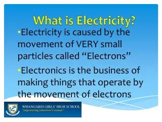
Introduction to Transistors • A transistor is an electrical device that is used to control current flow • It is made of three layers of semiconductor material • The construction is similar to the diode • Transistors often take the place of mechanical switches and relays • A transistor can be thought of as two diodes that share a common center layer
Introduction to Transistors The terms used for the 3 terminals of a transistor are: “the emitter”, “the collector”, and “the base”
Introduction to Transistors • The common schematic symbols used for transistors • The “emitter” always has a line with the arrow • The “base” is the heavy line at the bottom of the symbol • The “collector” is the line without the arrow
Transistor Construction • Adding a second layer of “P-type” material to the basic diode construction creates a “PNP” transistor • Adding a second layer of “N-type” material to the basic diode construction creates a “NPN” transistor
Basic Transistor Operation Supplying a positive/negative voltage to the base supplies the electrons needed for current flow
Transistor Operation “Amplification” aspects of a transistor
Amplifier Current Gain Transistors are small electrical controls that can perform large electrical tasks. “Saturation” level occurs when the maximum current flow of the circuit is reached.
“NPN” Transistor Operation • Supplying a small amount of current to the base creates current flow through the transistor (switched on) • Varying the amount of current supplied to the base varies its resistance and can vary the current flow through the emitter-collector • No current to base means no current will flow (switched off)
“PNP” Transistor Operation • Operates the same as the NPN type of transistor • One difference being the bias of the transistor in the circuit • Another being the polarity of the voltage in the circuit • Has the same amplification ability as the NPN • Operates as a electrical switch in the circuit
The Darlington Pair • Used when the current level supplied at the base is too small to allow sufficient current flow through the circuit • The first transistor is used to supply the necessary current to the base of the second transistor which controls the circuit
Solid State Relays • Used in situations where a “relay-type” circuit is needed • A “NPN” type transistor controls a “PNP” type transistor • Benefits of solid state relays include faster operation, and there are no moving parts to wear out
The Hall Effect Switch • With vanes “open” current flows to transistor • HEI reference voltage is less than 1 volt • With vanes “closed” no current flows to transistor • HEI reference voltage is 12 volts
SCR Silicon Controlled Rectifiers “SCR” Silicon Controlled Rectifiers are a type of transistor that by nature do not allow current to flow in either direction until triggered Unlike the transistors that act as switches, the SCR will continue to conduct current even after the trigger voltage has been removed The main source of voltage must be removed from the circuit to stop current flow through the SCR
The Silicon Controlled Rectifier • Schematic symbol is similar to diode • “The Anode” is positive • “The Cathode” is negative • “The Gate” is the trigger • A momentary voltage is all that is required to initiate and maintain current flow
SCR Construction & Operation • Constructed with alternating layers of semiconductor material • Similar to combining a PNP and a NPN type transistor • Functions by applying voltage to the “gate” terminal
LET’S REVIEW • WHAT ARE THE THREE LAYERS OF A TRANSISTOR? • WHAT IS THE SCHEMATIC SYMBOL FOR A TRANSISTOR? • WHAT ARE TWO FUNCTIONS OF TRANSISTORS? • WHAT ARE TWO THINGS THAT WILL DAMAGE A TRANSISTOR?
Elizabethtown Technical CollegeBEX100 – Basic ElectricityTransistorsSpring Semester 2001